3-88 2007 Buell Lightning: Engine
HOME
INSTALLATION
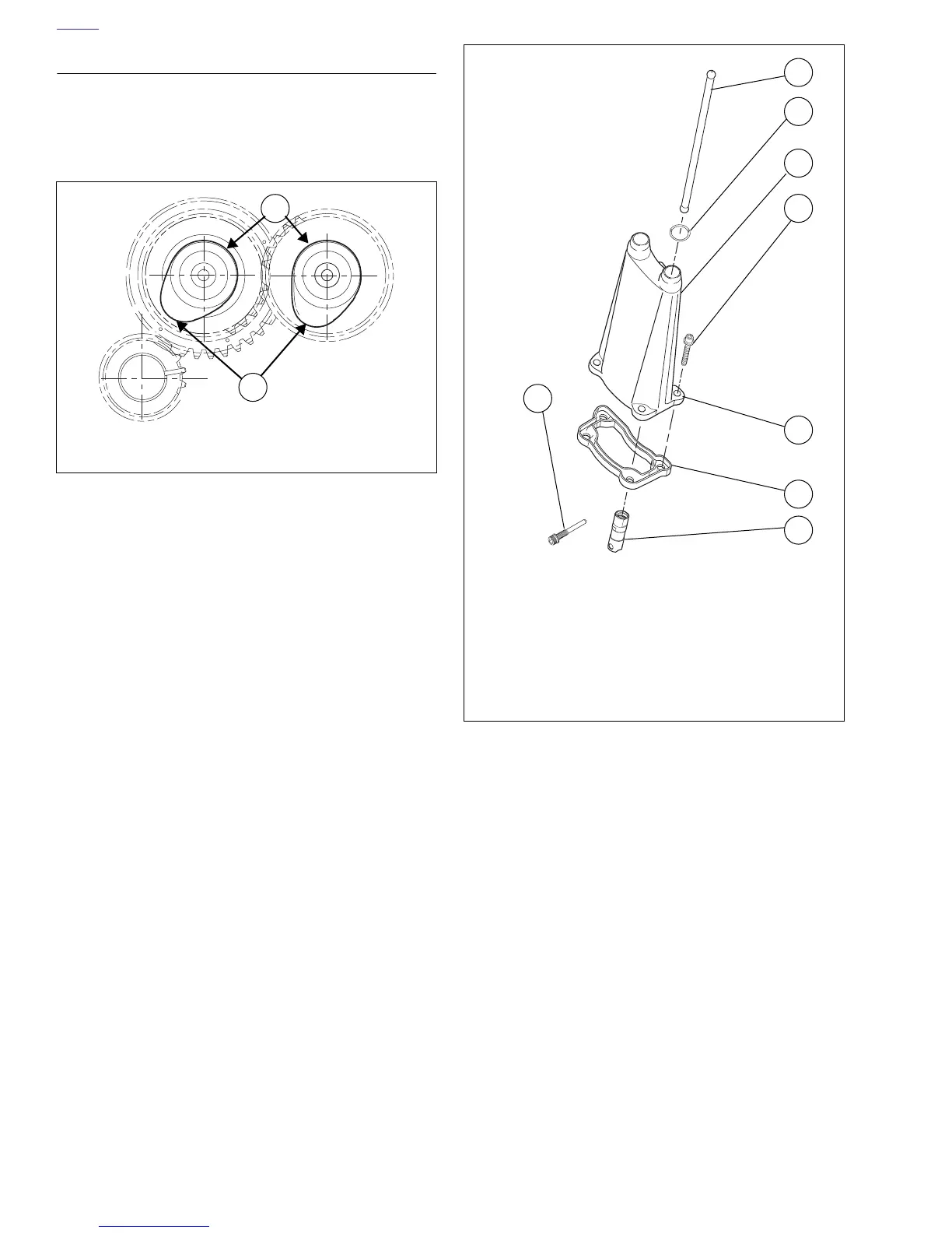
1. See Figure 3-124. Rotate engine so that both lifters from
the cylinder will be installed on the base circle of the
cam.
2. Apply a liberal amount of engine oil to each lifter assem-
bly (especially the roller needles) for smooth initial opera-
tion.
3. See Figure 3-125. Insert lifter into bore in crankcase.
Rotate lifter so that flats at upper end of lifter face the
front and rear of the engine. If the lifter is installed incor-
rectly, anti-rotation screws cannot be inserted.
4. Secure lifters in place.
a. Install anti-rotation screws with washers in the holes
in lifter block.
b. Tighten anti-rotation screws to 55-65 in-lbs (6-7
Nm).
NOTE
Before installing orings on top of pushrod cover be sure to
apply a small amount of clean engine oil to each oring.
5. See Figure 3-125. Install push rod cover.
a. Place new push rod cover gasket (6) over bottom of
push rod cover.
b. Position push rod cover onto crankcase.
c. Install screws (4) through holes in push rod cover
into tapped holes in crankcase. Tighten screws
evenly to 30-40 in-lbs (3-5 Nm).
d. Place new o-rings (2) on top of push rod cover (3).
6. Install push rods, cylinder head, lower and upper rocker
covers. See 3.6 CYLINDER HEAD.
7. Repeat process for remaining cylinder head.
Figure 3-124. Base Circle
2K
1K
b1037x3a
1
2
1. Base circle (lowest position)
2. Cam lobe (maximum lift)
Figure 3-125. Valve Lifter Service
b1048x3x
1
2
3
4
5
6
7
8
1. Push rod (exhaust)
2. O-ring
3. Push rod cover
4. Screws (4)
5. Push rod cover
6. Push rod cover gasket
7. Hydraulic lifter (tappet)
8. Anti-rotation screw
 Loading...


