2007 Buell Lightning: Engine 3-107
HOME
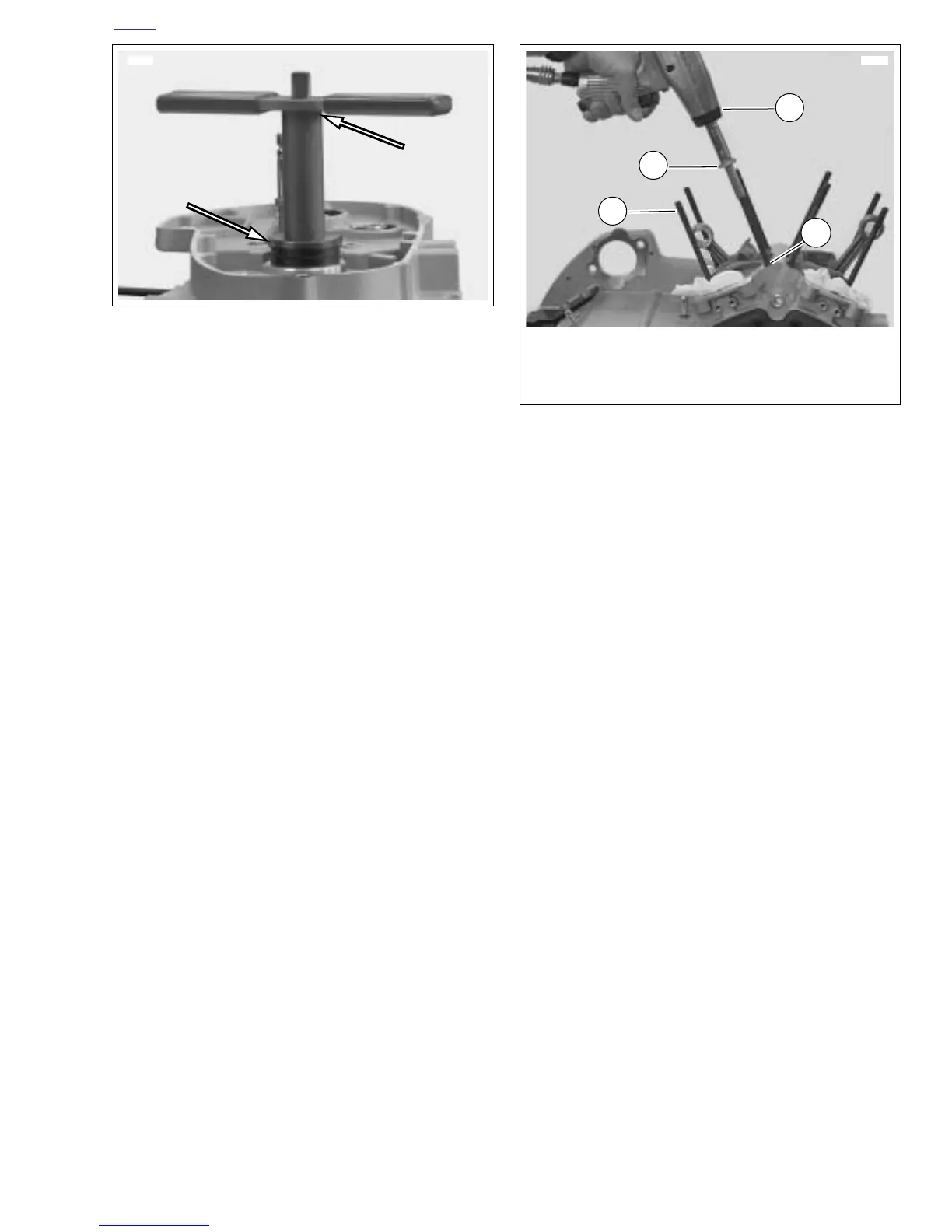
8. See Figure 3-155. Use SPROCKET SHAFT SEAL
INSTALLER (Part No. B-45676) to install sprocket shaft
seal.
a. Center seal/spacer driver over seal, so that the
sleeve (smaller OD) seats between seal wall and
garter spring.
b. Sparingly apply graphite lubricant to threads of pilot
shaft to ensure smooth operation.
c. Slide sleeve over pilot until sleeve contacts the oil
seal. Install handle on top of sleeve.
d. Rotate handle clockwise until tool bottoms on crank-
case lip. Remove tool from sprocket shaft.
e. Install new retaining ring in groove in left crankcase
next to oil seal.
9. See Figure 3-150. Install thrust washer (4) from the out-
side against the sprocket shaft bearing.
10. Install new spacer (1) in seal ID. With the thin (lipped)
side facing outward, center seal/spacer assembly over
bearing bore.
NOTE
Do not remove the spacer after installation or the new seal
will have to be discarded and the procedure repeated.
11. See Figure 3-156. Install cylinder studs.
a. Pack clean towels into crankcase opening.
b. Place a steel ball into a head screw.
c. The cylinder studs have a shoulder at the lower end.
Place the end of the stud without the shoulder into
the head screw.
d. Install the stud in the crankcase with the shoulder
end down. Use an air gun to drive the stud until the
shoulder reaches the crankcase.
e. Remove air gun. Use a torque wrench to tighten
stud to 10-20 ft-lbs (14-27 Nm).
12. Install piston and cylinder. See 3.7 CYLINDER AND PIS-
TON.
13. Install cylinder head. See 3.6 CYLINDER HEAD.
14. Install cam gears, gearcase cover, lifter guides and lift-
ers. See 3.18 GEARCASE COVER AND CAM GEARS.
15. Install oil pump. See 3.15 OIL PUMP.
16. Install starter. See 5.7 STARTER.
17. Install shift shaft. See 6.15 SHIFTER SHAFT.
18. Install stator. See 7.8 ALTERNATOR.
19. Install all primary drive components. This includes
engine sprocket, primary chain, complete clutch assem-
bly, engine sprocket nut and mainshaft nut. See 6.5 PRI-
MARY CHAIN.
20. Install primary cover. See 6.2 PRIMARY COVER.
NOTE
Be sure to refill transmission to proper level with fresh lubri-
cant. See 1.8 CLUTCH.
21. To reinstall engine in frame see 3.5 ENGINE INSTALLA-
TION.
Figure 3-155. Sprocket Shaft Seal/Spacer Installer
(Part No. HD-42579 and B-45676)
8761
Figure 3-156. Cylinder Studs
1
4
1. Head Screw with ball inside
2. Cylinder stud
3. Shoulder on cylinder stud
4. Air gun
2
3
8799