2007 Buell Lightning: Drive/Transmission 6-33
HOME
MAINSHAFT/COUNTERSHAFT
NOTES
●
As the transmission runs, each part develops a certain
wear pattern and a kind of “set” with its mating parts. For
this reason, it is important that each component be rein-
stalled in its original location and facing its original direc-
tion.
●
See Figure 6-61. As each component is removed, place
it on a clean surface in the exact order of removal.
MAINSHAFT DISASSEMBLY
NOTES
●
Mainshaft 2nd and 3rd gears are integral to the shaft.
●
Mainshaft 1st gear is directional. Mark gear when
removed for correct installation.
●
Once the transmission assembly has been pressed out
of the left crankcase half, the mainshaft and countershaft
assemblies can be serviced separately.
●
All thrust washers are one common part number. This
transmission requires no shimming.
Wear safety glasses or goggles when removing or install-
ing retaining rings. Retaining rings can slip from the pli-
ers and could be propelled with enough force to cause
serious eye injury. (00312a)
NOTE
Use correct retaining ring pliers and correct tips. Verify that
tips are not excessively worn or damaged.
1. See Figure 6-62. Remove 1st gear (1).
2. Use RETAINING RING PLIERS (Part No. J-5586-A) to
expand and remove retaining ring (2). Discard retaining
ring.
3. Slide thrust washer (3) off end of mainshaft.
4. Remove 4th gear (4) and split bearing (5). Discard bear-
ing.
Cleaning And Inspection
Compressed air can pierce the skin and flying debris
from compressed air could cause serious eye injury.
Wear safety glasses when working with compressed air.
Never use your hand to check for air leaks or to deter-
mine air flow rates. (00061a)
1. Clean all parts in cleaning solvent and blow dry with
compressed air.
2. Check gear teeth for damage. If gears are pitted, scored,
rounded, cracked or chipped, they should be replaced.
3. Inspect the engaging dogs on the gears. Replace the
gears if dogs are rounded, cracked, battered, chipped or
dimpled.
Figure 6-61. Transmission Parts Identification
11331
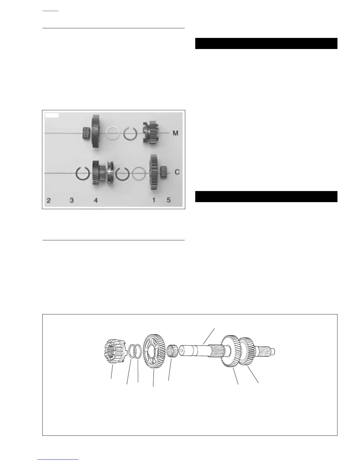
Figure 6-62. Transmission Mainshaft Assembly Once Removed from Left Crankcase/Disassembly
x0599a6x
Left Crankcase
1. Mainshaft 1st gear
2. Retaining ring
3. Thrust washer
4. Mainshaft 4th gear
5. Split bearing
6. Mainshaft
7. Mainshaft 3rd gear
*
8. Mainshaft 2nd gear*
5
8
7
4
3
1
6
2
* Mainshaft 2nd and 3rd gears are integral to the shaft.