6-54 2007 Buell Lightning: Drive/Transmission
HOME
INSTALLATION
1. See Figure 6-101. Install transmission sprocket (4) with
secondary drive belt onto main drive gear (5).
2. Place transmission in neutral.
3. Apply a few drops of LOCTITE 271 (red) to the left-hand
threads of transmission sprocket nut (3) and lightly coat
the washer-faced side with clean H-D 20W50 engine oil.
Wipe off any excess oil.
4. Position nut with washer-faced side facing transmission
sprocket. Turn the nut counterclockwise to install it onto
main drive gear.
NOTE
Use the P3/Blast SPROCKET HOLDING TOOL (Part No. B-
43982) with the spacer and fastener from the 2003 Firebolt
SPROCKET LOCKING TOOL (B-45659) to hold the sprocket.
5. See Figure 6-103. Install SPROCKET HOLDING TOOL
(Part No. B-43982) as shown.
6. Using MAINSHAFT LOCKNUT WRENCH (Part No. HD-
94660-37B) and a torque wrench, tighten sprocket nut to
50 ft-lbs (67.8 Nm) INITIAL TORQUE ONLY.
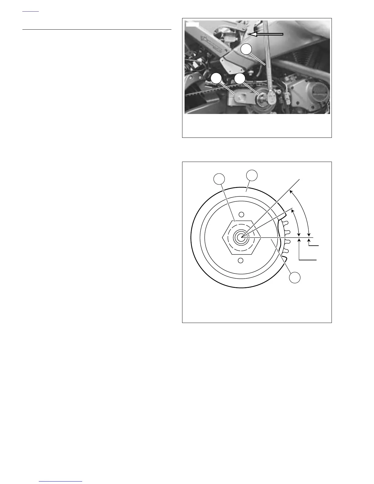
7. See Figure 6-104. Scribe a line on the transmission
sprocket nut and continue the line on the transmission
sprocket as shown.
8. Tighten the transmission sprocket nut an additional 30°-
40°.
NOTE
Maximum allowable tightening of sprocket nut is 45° of coun-
terclockwise rotation, after initially tightening to 50 ft-lbs. Do
not loosen sprocket nut while attempting to align the screw
holes. The lockplate has four screw holes and can be turned
to either side, so you should be able to find a position without
having to additionally tighten the nut. If you cannot align lock-
plate and sprocket screw holes, nut may be additionally tight-
ened to 45° as specified above. Tightening too much or too
little may cause the nut to come loose during vehicle opera-
tion.If you cannot align lockplate and sprocket screw holes,
nut may be additionally tightened until screw holes align.
NEVER LOOSEN nut to align the screw holes.
9. See Figure 6-101. Install lockplate over nut so that two of
lockplate’s four drilled holes (diagonally opposite) align
with sprocket’s two tapped holes.
10. See Figure 6-101. Install two socket head screws
through aligned holes of lockplate and into tapped holes
of sprocket. Tighten to 90-110 in-lbs (10.2-12.4 Nm).
NOTE
See Figure 6-101. The original equipment socket head
screws (1) have thread-locking compound applied to them.
Since this compound remains effective for about three
removal/installation cycles, the original screws may be
reused up to three times. After the third removal/installation
cycle, replace both screws with new screws identical to the
original.
11. Install idler pulley. See IDLER PULLEY INSTALLATION-
under 6.6 DRIVE BELT SYSTEM.
Figure 6-103. Transmission Sprocket Tightening
(Typical)
Figure 6-104. Aligning Transmission Sprocket
1. Sprocket holding tool
2. Mainshaft locknut wrench
3. Torque wrench
11979
2
1
3
45°
30°
a0163x6x
1. Transmission sprocket nut
2. Transmission sprocket
3. Line scribed on nut and sprocket
3
2
1