2007 Buell Lightning: Electrical 7-31
HOME
CLEANING AND INSPECTION
CAUTION
Do not strike or drop alternator rotor or damage to mag-
net adhesive may occur. Magnet adhesive damage can
result in rotor failure.
1. Clean rotor with a petroleum-base solvent. Remove all
foreign material from rotor magnets. Replace rotor if rotor
magnets are cracked or loose.
2. Clean stator by wiping with a clean cloth.
3. Examine stator leads for cracked or damaged insulation.
NOTE
The rotor and stator can be replaced individually if either is
damaged.
ASSEMBLY/INSTALLATION
Depending on whether the rotor, the stator, or both the rotor
and stator were removed/disassembled, perform the applica-
ble procedures which follow:
1. See Figure 7-36. Feed stator wiring (4) with attached
grommet (3) into open grommet hole in left crankcase
half.
2. Apply a light coating of clean engine oil or chaincase
lubricant to grommet. Install grommet into hole in left
crankcase half.
NOTE
Stator TORX screws contain a thread locking compound. Do
not reuse existing screws. Always use new screws with the
proper thread locking compound. Loss of torque on TORX
fasteners could result in alternator damage.
3. Position stator (2) on left crankcase half. Secure stator
using four
new
TORX screws (1). Tighten TORX screws
to 30-40
in-lbs
(3-4 Nm).
4. Install retainer plate with
new
fasteners and tighten to 56
in-lbs
(6.3 Nm).
5. Route stator wiring (4) behind rear cylinder and in front of
transmission breather hose. See 7.26 SPROCKET
COVER WIRING for remaining wire routing information.
a. Route stator wire (4) between The vent oil line and
the return oil line.
b. Install connector (5) [46] onto the stator wiring (4)
using cavities 1, 2, 3 of connector (5) [446]. See B.2
DEUTSCH ELECTRICAL CONNECTORS for addi-
tional information.
NOTE
See 7.26 SPROCKET COVER WIRING for remaining wire
routing information.
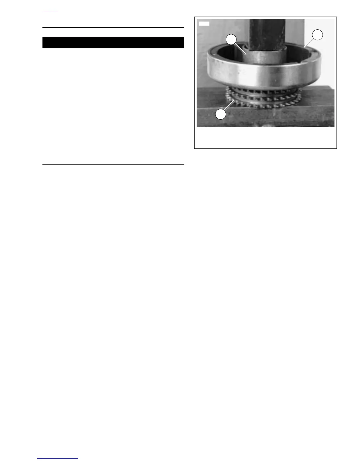
6. See Figure 7-37. Attach rotor to sprocket.
a. Position rotor (3) on sprocket (1). Align holes in
sprocket with holes in rotor.
b. Insert eight
new
mounting fasteners through rotor
and start fasteners into tapped holes in sprocket.
c. Position a section of pipe (2) with an inside diameter
larger than the sprocket mounting hub over center of
rotor. Press rotor onto sprocket. Tighten fasteners to
120-140
in-lbs
(13.5-15.8 Nm).
7. Install clutch assembly, primary chain and engine
sprocket/rotor assembly as a unit. See 6.5 PRIMARY
CHAIN.
8. Install primary cover. See 6.2 PRIMARY COVER.
9. Connect negative battery cable.
10. Test charging system. See 7.7 CHARGING SYSTEM.
Figure 7-37. Pressing Rotor onto Sprocket
3560
1. Sprocket
2. Pipe section
3. Rotor
1
3
2