7-50 2007 Buell Lightning: Electrical
HOME
INSTALLATION
Front
1. See Figure 7-58. Insert bullet connectors and wiring
through hole in front module.
2. Install turn signal using lockwasher and jam nut. Tighten
fastener to 25-28 in-lbs (2.8-3.2 Nm).
3. Attach bullet connectors on turn signal wires as shown in
Figure 7-62.
1WARNING1WARNING
Be sure that all lights and switches operate properly
before operating motorcycle. Low visibility of rider can
result in death or serious injury. (00316a)
4. Check turn signals for proper operation. If operation fails,
reread procedure and verify that all steps were per-
formed.
a. Turn ignition key switch to ON.
b. Activate left turn signals using switch on left handle-
bar. Front and rear left turn signals must flash.
c. Activate right turn signals using switch on left han-
dlebar. Front and rear right turn signals must flash.
d. Turn ignition key switch to OFF.
5. Install windscreen. See 2.43 WINDSCREEN.
Rear
1. See Figure 7-62. Insert bullet connectors through center
tail section.
2. Install reflector bracket.
NOTE
Be sure tab on turn signal fits into hole in reflector bracket
and tab on reflector bracket fits into hole in enter tail section.
3. See Figure 7-60. Attach turn signal using lockwasher
and fastener (4).Tighten fastener to 25-28 in-lbs (2.8-3.2
Nm).
4. Attach bullet connectors on turn signal wires as shown in
Figure 7-62.
1WARNING1WARNING
Be sure that all lights and switches operate properly
before operating motorcycle. Low visibility of rider can
result in death or serious injury. (00316a)
5. Check turn signals for proper operation. If operation fails,
reread procedure and verify that all steps were per-
formed.
a. Turn ignition key switch to ON.
b. Activate left turn signals using switch on left handle-
bar. Front and rear left turn signals must flash.
c. Activate right turn signals using switch on left han-
dlebar. Front and rear right turn signals must flash.
d. Turn ignition key switch to OFF.
1WARNING1WARNING
After installing seat, pull upward on front of seat to be
sure it is in locked position. While riding, a loose seat can
shift causing loss of control, which could result in death
or serious injury. (00070a)
6. Install seat. See 2.44 SEAT.
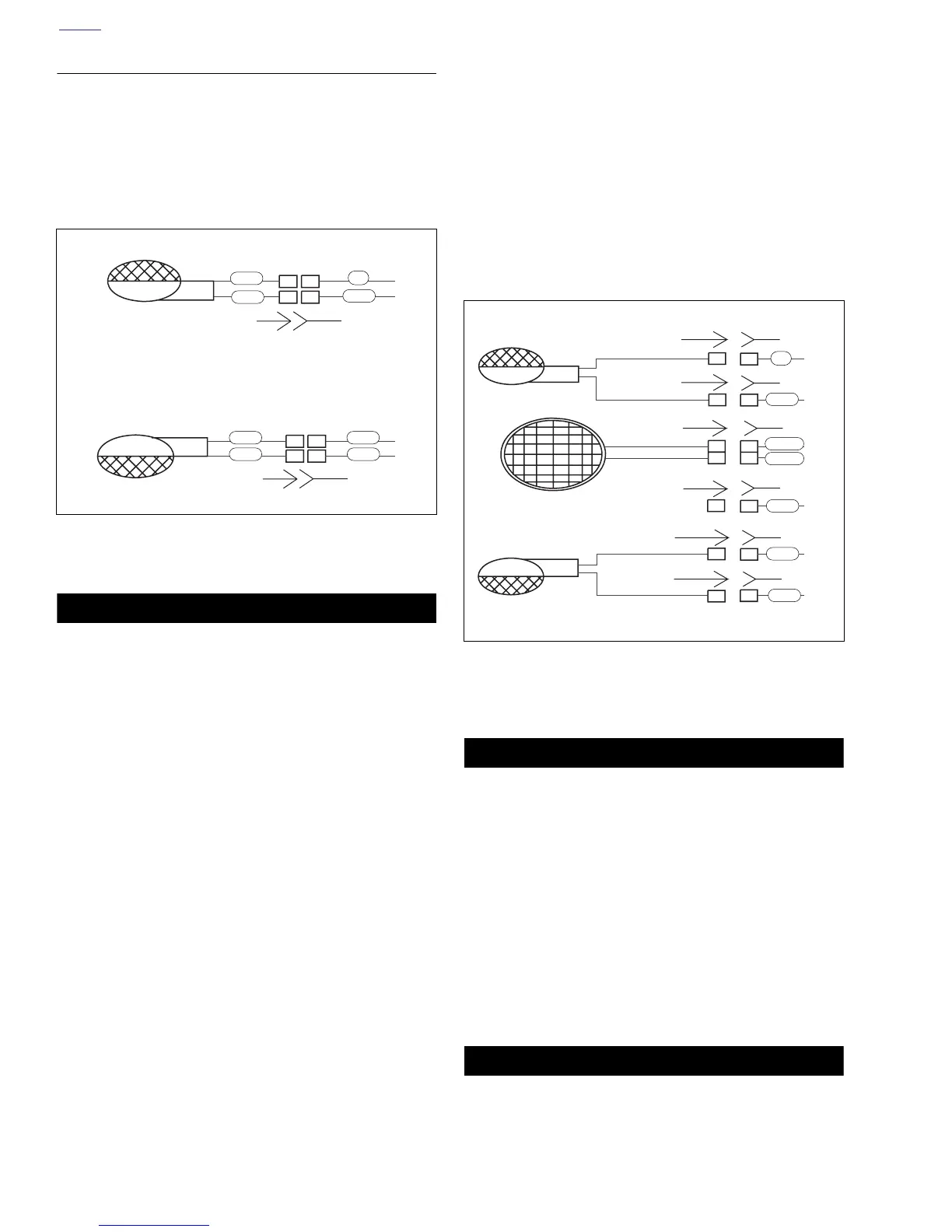
Figure 7-61. Front Turn Signal Connections
22
11
11
22
[31B]
[31A]
[31B]
[31A]
b1100x7x
Right Turn
Signal
Left Turn
Signal
BK
V
BE
BK
BK
BE
BK
BN
Figure 7-62. Rear Turn Signal Connections
1
1
2
2
2
2
1
1
1
2
1
2
1
1
[19A]
[93A] [93B]
[93B]
[93A]
[18A] [18A]
[18A]
[18A]
[19A]
[19B]
[19B]
Right turn signal
Tail lamp
b1099x7x
Left turn signal
V
BK
BK
BN
Tail lamp ground
BK
O/W
R/Y