2007 Buell Lightning: Chassis 2-19
HOME
NOTES
● Press the rotor side bearing in first ensuring it is seated
on the shoulder of the wheel. Followed by pressing the
alternate side bearing until it contacts the spacer.
● See Figure 2-23. When installing rear wheel bearings it
is necessary to use the FORCING SCREW (1) from the
STEERING HEAD BEARING RACE INSTALLER (Part
No. HD-39302).
● The Wheel Bearing Remover and Installer (B-43993-50)
consists of the Front Wheel Bearing Remover Collet (B-
43993-7), Rear Wheel Bearing Remover Collet (B-
43993-8), Rear Wheel Bearing Installer (B-43993-9),
Front Wheel Bearing Installer (B-43993-10) and Backing
Plates (B-43993-11 front wheel) and (B-43993-12 rear
wheel).
● The procedure for the rear wheel bearing installation is
the same as front wheel bearing installation. See Bear-
ing Installation in 2.5 FRONT WHEEL.
1. Install wheel bearing (3) on rotor side of motorcycle.
2. Install rear wheel spacer (4).
3. Install wheel bearing (3) on sprocket side of motorcycle.
CAUTION
Do not re-use sprocket mounting screws. Re-using
sprocket mounting screws can result in torque loss and
damage to the sprocket and/or belt assembly. (00480b)
4. Install sprocket.
a. Position sprocket (6) on wheel (5) keeping lip of
sprocket facing the inside.
b. Install new sprocket fasteners (7) and washers tight-
ening to 35-37 ft-lbs (48-50 Nm).
CAUTION
Do not re-use brake disc screws. Re-using disc screws
can result in torque loss and damage to rotor and/or
brake assembly. (00319b)
5. Install rear rotor (2).
a. Position rear brake rotor (2) on wheel (5).
b. Install brake rotor (2) with new rotor mounting fas-
teners (1) and tighten to 25-27 ft-lbs (34-37 Nm).
INSTALLATION
1. Center rear wheel in the swingarm at the same time slid-
ing the drive belt onto the rear sprocket.
2. With wheel centered in swingarm, lower bike to align
swingarm and wheel hub.
3. Apply ANTI-SEIZE LUBRICANT to hole in right side of
swingarm where rear axle slides through.
4. See Figure 2-24. Coat the axle with ANTI-SEIZE LUBRI-
CANT.
5. Slide axle through right side of swing arm and wheel hub
and thread partially into swingarm on left side.
6. Install idler pulley. See DRIVE BELT INSTALLATION in
section 6.6 DRIVE BELT SYSTEM.
NOTE
Never tighten rear axle with swingarm brace removed.
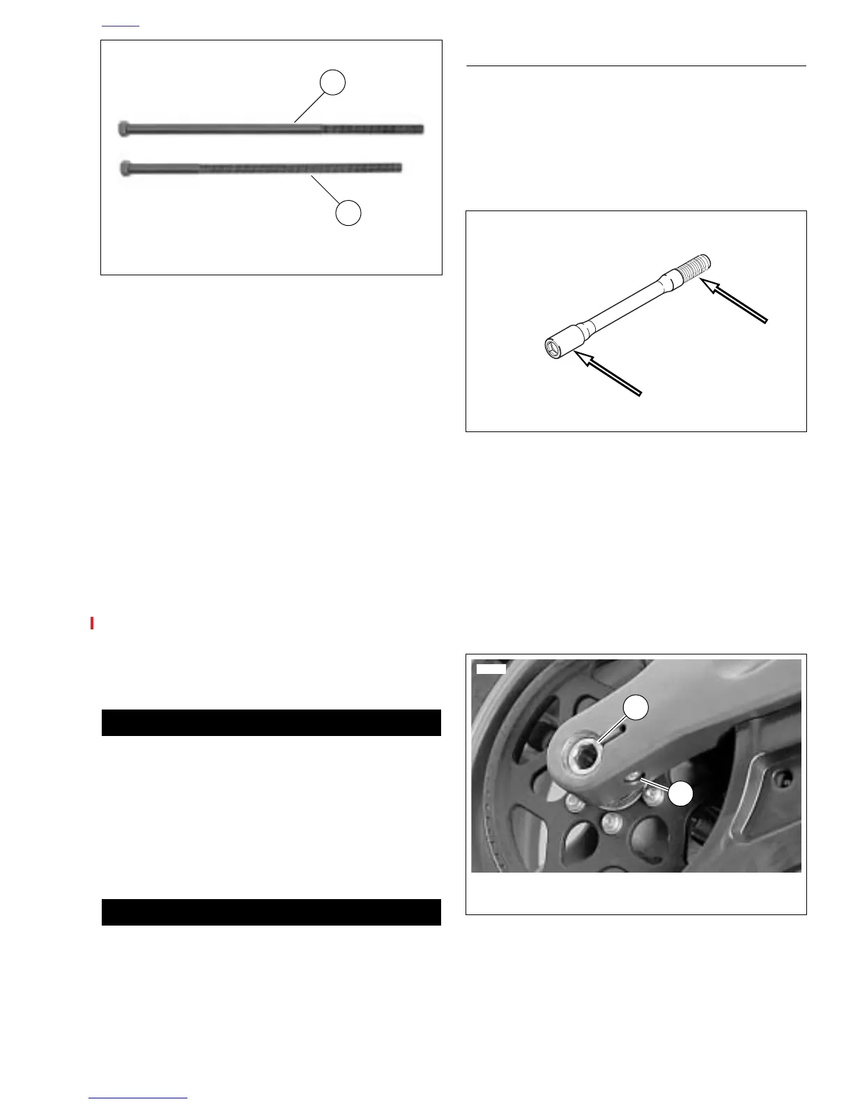
7. See Figure 2-25. Tighten rear axle (1) to 23-27 ft-lbs
(31.2-36.6 Nm), back off two full turns and then retighten
to 48-52 ft-lbs (65.1-70.5 Nm).
8. Tighten pinch fastener (2) on right side of swingarm to
40-45 ft-lbs (54-61 Nm).
Figure 2-23. Forcing Screws Used for Front and Rear
Wheel Bearing Installation
10096
1. Rear wheel forcing screw
2. Front wheel forcing screw (Part No. 280856)
1
2
Figure 2-24. Anti-Seize Lubricant Location
Figure 2-25. Rear Wheel Mounting, Right Side
11810
2
1. Axle
2. Pinch bolt fastener
1