2-30 2007 Buell Lightning: Chassis
HOME
INSTALLATION
1. See Figure 2-37. Install front brake lamp switch (11).
a. Install brake lamp switch (11) with switch fastener
(10) and tighten to 7-10 in-lbs (0.8-1.0 Nm).
b. Connect brake switch terminal (12) to brake lamp
switch (11).
c. Test switch action. Tang on switch must release
when hand lever is moved.
2. Install master cylinder to handlebar by fastening clamp
with fasteners. Position for rider posture and tighten to
80-90 in-lbs (9-10 Nm).
11WARNING1WARNING
Use only new copper crush banjo washers (See Parts
Catalog for Part No.) with D.O.T. 4 brake fluid. Earlier sil-
ver banjo washers are not compatible with D.O.T. 4 fluid
and will not seal properly over time. Failure to comply
may adversely affect braking ability and lead to brake
failure which could result in death or serious injury.
11WARNING1WARNING
To avoid leakage, verify that banjo washers, banjo bolt,
hydraulic brake line and master cylinder bore are com-
pletely clean.
3. See Figure 2-37. Connect brake line to master cylinder
using two new copper washers (15) and banjo bolt (13)
(metric) and tighten to 16-20 ft-lbs (22-27 Nm).
4. See Figure 2-40. Verify brake lamp switch wires are tight.
5. See Figure 2-37. Remove two master cylinder cover
screws (1), cover (2) and cover gasket (3).
6. Protect body work from brake fluid.
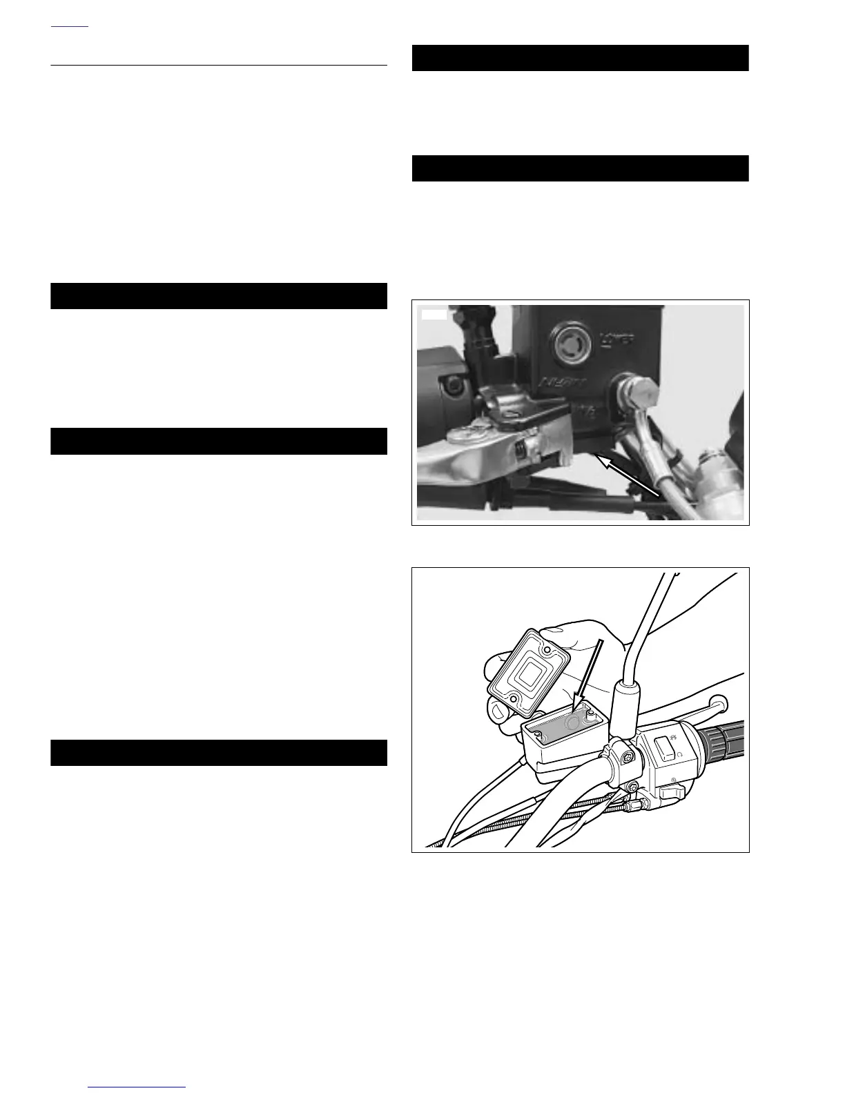
7. See Figure 2-41. With the master cylinder in a level posi-
tion, add D.O.T. 4 BRAKE FLUID. Bring fluid level to
within 1/8 in. (3.2 mm) of molded boss inside front mas-
ter cylinder reservoir.
11WARNING1WARNING
A plugged or covered relief port can cause brake drag or
lock-up, which could lead to loss of control, resulting in
death or serious injury. (00288a)
8. Verify proper operation of the master cylinder relief port.
Actuate the brake lever with the reservoir cover removed.
A slight spurt of fluid will break the surface if all internal
components are working properly.
9. Bleed brake system. See 1.6 BRAKE SYSTEM MAINTE-
NANCE.
10. See Figure 2-37. Attach master cylinder cover (2) and
cover gasket (3). Tighten two cover fasteners (1) to 9-
13 in-lbs (1.0-1.5 Nm).
NOTE
For XB9SX see 2.25 DEFLECTORS/HANDLEBARS
(XB9SX).
11WARNING1WARNING
After repairing the brake system, test brakes at low
speed. If brakes are not operating properly, testing at
high speeds can cause loss of control, which could
result in death or serious injury. (00289a)
11WARNING1WARNING
Be sure that all lights and switches operate properly
before operating motorcycle. Low visibility of rider can
result in death or serious injury. (00316a)
11. Turn ignition key switch to ON. Apply brake hand lever to
test brake lamp operation. Turn ignition key switch to
OFF.
Figure 2-40. Front Brake Light Switch Connector
Figure 2-41. Brake Fluid Level
(Standard Brake Reservoir Shown)
8923
b0613x2x