2-38 2007 Buell Lightning: Chassis
HOME
DISASSEMBLY
1. See Figure 2-53. Slide rubber boot on rod assembly (3)
away from master cylinder body (1).
2. Depress rod assembly (3) and remove internal circlip (2).
Discard circlip.
3. Remove piston assembly (4) from master cylinder body
(1).
4. Loosen adjuster locknut on the rod assembly (3).
5. Remove the clevis from the rod assembly (3).
NOTE
Do not disassemble master cylinder unless problems are
experienced. Discard all seals during the disassembly proce-
dure. Install a complete rebuild kit upon assembly.
CLEANING AND INSPECTION
11WARNING1WARNING
Use denatured alcohol to clean brake system compo-
nents. Do not use mineral-based solvents (such as gaso-
line or paint thinner), which will deteriorate rubber parts
even after assembly. Deterioration of these components
can cause brake failure, which could result in death or
serious injury. (00291a)
1. Thoroughly clean master cylinder and all brake system
components. Stand master cylinder on wooden block or
towel to protect seating surfaces.
a. Examine walls of master cylinder reservoir for
scratches and grooves. Replace if damaged.
b. Verify that vent holes on master cylinder are com-
pletely open and free of dirt or debris.
2. Inspect boot on front of master cylinder for cuts, tears or
general deterioration. Replace if necessary.
ASSEMBLY
1. Obtain PISTON ASSEMBLY KIT.
2. See Figure 2-53. Assemble new piston components
placing small end of spring behind primary seal of piston
(4).
3. Lubricate master cylinder body (1) and piston seals (5)
with D.O.T. 4 BRAKE FLUID.
4. Place round side of rod assembly (3) over piston.
Depress piston (4) into master cylinder body (1) and
secure with a new circlip (2).
11WARNING1WARNING
Circlip must be snapped into the groove of the master
cylinder body. If the circlip is not properly installed,
improper brake operation could result in death or serious
injury.
5. Tuck rubber boot on rod assembly (3) into master cylin-
der body (1).
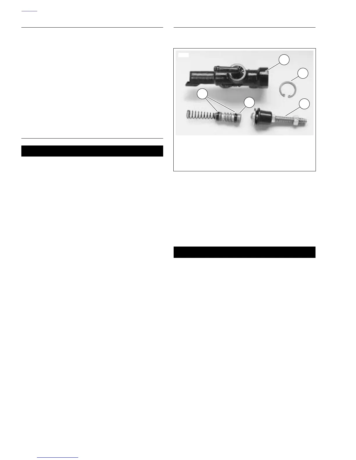
Figure 2-53. Master Cylinder Internal
6506
1. Master cylinder body
2. Snap ring
3. Rod assembly
4. Piston assembly
5. Seals
1
2
3
4
5