2-26 2007 Buell P3: Chassis
HOME
ASSEMBLY
1. See Figure 2-33. Check piston assembly components.
a. Small end of spring (1) sits behind primary cup (2).
Large side of primary cup faces spring.
b. Secondary cup (3) sits within ridge at middle of pis-
ton (4).
2. Insert piston assembly, spring first, into master cylinder.
Secure with a new snap ring (6).
3. Install ridge on boot (5) into groove on piston (4).
4. See Figure 2-28. Install front brake hand lever.
a. Align hole in lever with hole in master cylinder
assembly.
b. Lubricate pivot bolt (2) with Loctite Anti-Seize.
c. Install pivot bolt through top of assembly. Tighten to
4-13 in-lbs (0.5-1.5 Nm).
d. Install nut (1) (metric). Tighten to 44-62 in-lbs (5-
7 Nm).
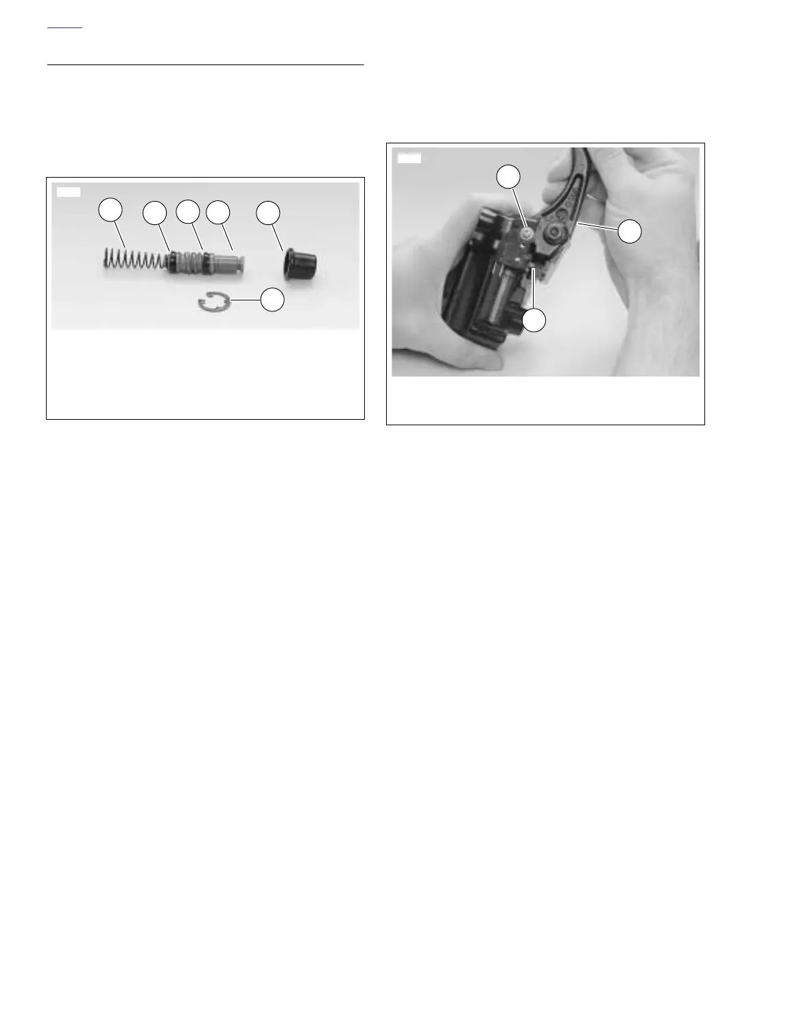
5. See Figure 2-29. Install front brake lamp switch (7).
a. Attach front brake switch with screw, washer and
lockwasher (1). Tighten to 7-13 in-lbs (0.8-1.5 Nm).
b. See Figure 2-34. Test switch action. Tang (3) on
switch must release when hand lever (2) is moved.
Figure 2-33. Piston Assembly
6491
1. Spring
2. Primary cup
3. Secondary cup
4. Piston
5. Boot
6. Snap ring
1
2
3
4
6
5
Figure 2-34. Testing Hand Lever
6493
1
3
2
1. Screw, lockwasher and washer
2. Hand lever
3. Tang