Appendix B: Wiring B-5
HOME
Insert Terminals into Housings
NOTE
See Figure B-3. Cavity numbers are stamped into the sec-
ondary locks of both the socket and pin housings. Match the
wire color to the cavity number found on the wiring diagram.
1. Hold the terminal so the catch faces the tang in the
chamber. Insert the terminal into its numbered cavity
until it snaps in place.
NOTES
●
Up and down can be determined by the position of the
release button, the button is the top of the connector.
●
On the pin side of the connector, tangs are positioned at
the bottom of each cavity, so the slot in the pin terminal
(on the side opposite the crimp tails) must face down-
ward.
●
On the socket side, tangs are at the top of each cavity, so
the socket terminal slot (on the same side as the crimp
tails) must face upward.
2. Gently tug on wire end to verify that the terminal is
locked in place.
3. Rotate the hinged secondary lock inward until tabs fully
engage latches on both sides of connector.
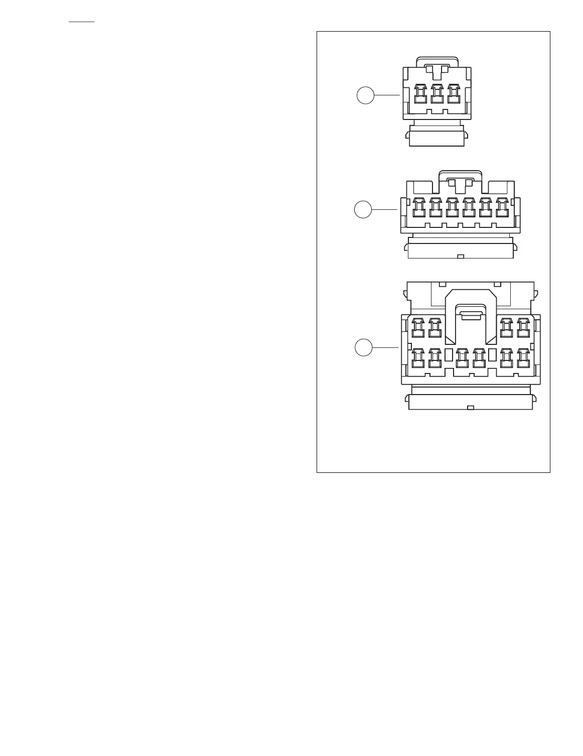
Figure B-3. Cavity Numbers on Secondary Locks
(socket housings shown)
– AMP
123
– AMP
123456
56 78 910
43 2 1
1
2
3
f2621x1x
1. 3-place housing
2. 6-place housing
3. 10-place housing