6-14 2007 Buell P3: Drive/Transmission
HOME
ASSEMBLY
Clutch Pack
1. See Figure 6-14. Install the clutch pack which consists of
five fiber plates and five steel plates, into the clutch hub.
The order of plate assembly, from inboard to outboard, is
as follows:
St - F - St - F - St - F - St - F - St - F
(St = St
eel plate, F = Fiber plate)
IMPORTANT NOTE
See Figure 6-13. Turn compressing tool handle only the
amount required to install spring seat and snap ring.
Excessive compression of diaphragm spring could dam-
age clutch pressure plate.
2. Place assembly of spring seat, new snap ring, dia-
phragm spring, pressure plate, adjusting screw compo-
nents and compressing tool onto clutch hub and against
clutch pack.
a. See Figure 6-19. Align square openings of pressure
plate and diaphragm spring so that the assembly
can be installed over prongs of clutch hub.
b. Position spring seat with its larger O.D. side toward
diaphragm spring.
c. See Figure 6-20. Place a wrench on the clutch
spring forcing screw flats to prevent the forcing
screw from turning.
d. Turn compressing tool handle clockwise until dia-
phragm spring compresses just enough to install
spring seat and new snap ring into the groove in
clutch hub prongs.
e. With snap ring positioned against outboard side of
spring seat, and fully seated in groove of clutch hub,
carefully loosen and remove compression tool.
Primary Drive
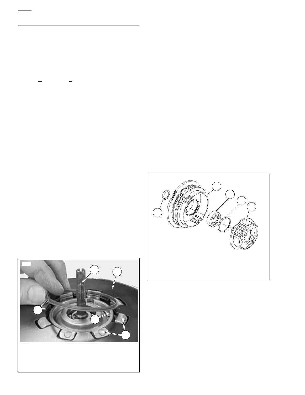
1. See Figure 6-20. Assemble clutch hub and shell if neces-
sary.
a. Press new bearing in clutch shell. Secure bearing
with a new retaining ring.
b. Press inboard end of clutch hub into shell bearing.
Secure with new retaining ring on end of hub.
2. Assemble pressure plate hardware.
a. See Figure 6-16. Place bearing inside release plate.
Insert adjusting screw through bearing and release
plate. Secure with new retaining ring.
b. See Figure 6-19. Position diaphragm spring with its
concave side facing toward pressure plate onto
pressure plate assembly.
c. Insert adjusting screw assembly into pressure plate.
Secure with large retaining ring.
d. Position spring seat with its larger O.D. side toward
diaphragm spring.
3. Attach tools to compress clutch diaphragm spring. Do
not tighten compressing tool against diaphragm spring at
this time. See Step 2 of CLUTCH PACK under 6.4 PRI-
MARY DRIVE/CLUTCH.
4. Install the clutch pack. Follow all instructions of CLUTCH
PACK under 6.4 PRIMARY DRIVE/CLUTCH.
Figure 6-19. Spring Seat Installation
5
6253
1
2
1. Diaphragm spring (pressure plate below)
2. Prongs on clutch hub
3. Retaining ring
4. Adjusting screw assembly
5. Spring seat
4
3
Figure 6-20. Clutch Hub and Shell Assembly
a0115x6x
1. Clutch hub
2. Retaining ring
3. Bearing
4. Clutch shell
5. Retaining ring
1
2
3
4
5