2007 Buell P3: Electrical 7-31
HOME
System Relay
See Figure 7-36. The system relay is in the relay block which
is located on the left side under the seat. Test the relay as fol-
lows:
1. Remove seat. See 2.28 SEAT.
2. Unplug relay from connector. Test the relay in the same
fashion as the starter relay. See 5.6 STARTER SYSTEM
TESTING.
3. Replace the relay with a new relay if necessary. Install
relay to frame with new rivet and washer.
Starter Relay
The starter relay is located on the right side of the motorcycle,
underneath the seat by the flasher relay.
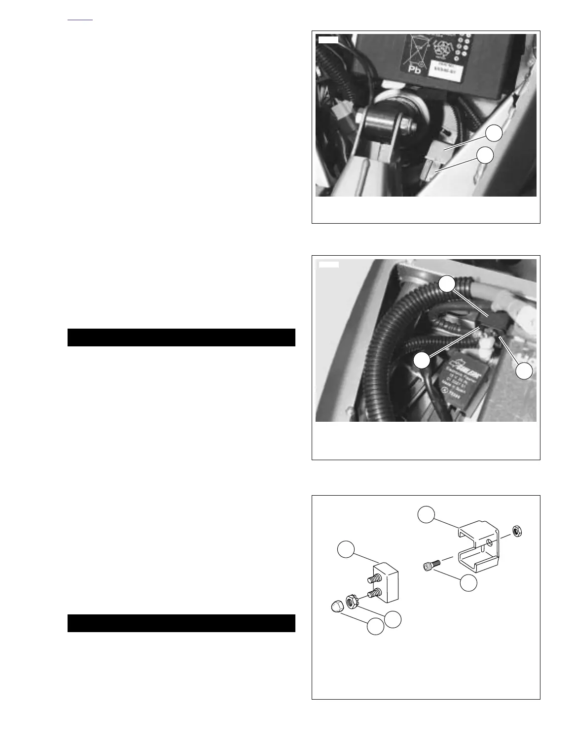
Main Circuit Breaker
See Figure 7-37. Attached to the frame above the battery, the
main circuit breaker is between the ignition key switch and the
battery. Remove the main circuit breaker as follows:
1. Remove seat. See 2.28 SEAT.
11WARNING1WARNING
To prevent accidental vehicle start-up, which could
cause death or serious injury, disconnect negative (-)
battery cable before proceeding. (00048a)
2. Disconnect battery negative cable from battery.
3. See Figure 7-38. Remove acorn nuts, nuts with lock
washers and wire leads from circuit breaker studs. Tag
wire leads for ease of assembly.
4. See Figure 7-37. Remove circuit breaker from circuit
breaker bracket by carefully prying tab, located on left
side, open and sliding circuit breaker out.
NOTE:
Bank Angle Sensor will require reinstallation if bracket is
removed. See 7.5 BANK ANGLE SENSOR.
5. Install in the reverse order. Tighten screw (if bracket was
removed) to 25-27 in-lbs (2.8-3.1 Nm). Tighten metal nut
to 15-18 in-lbs (1.7-2 Nm). Tighten plastic acorn nuts to
1-3 in-lbs (0.1-0.3 Nm).
6. Connect negative battery cable to battery terminal.
Tighten fastener to 72-96 in-lbs (8-11 Nm).
11WARNING1WARNING
After installing seat, pull upward on front of seat to be
sure it is in locked position. While riding, a loose seat can
shift causing loss of control, which could result in death
or serious injury. (00070a)
7. Install seat. See 2.28 SEAT.
Figure 7-36. System Relay
Figure 7-37. Circuit Breaker
Figure 7-38. Circuit Breaker Installation
7803
1. System relay
2. Connector [171]
1
2
7811
1. Bracket
2. Tab
3. Circuit breaker (30A)
1
2
3
a0237x7x
1. Circuit breaker (30A)
2. Bracket
3. Screw
4. Nut with lock washer (2)
5. Acorn nut (2)
2
4
1
3
5