7-32 2007 Buell P3: Electrical
HOME
Ignition Fuse
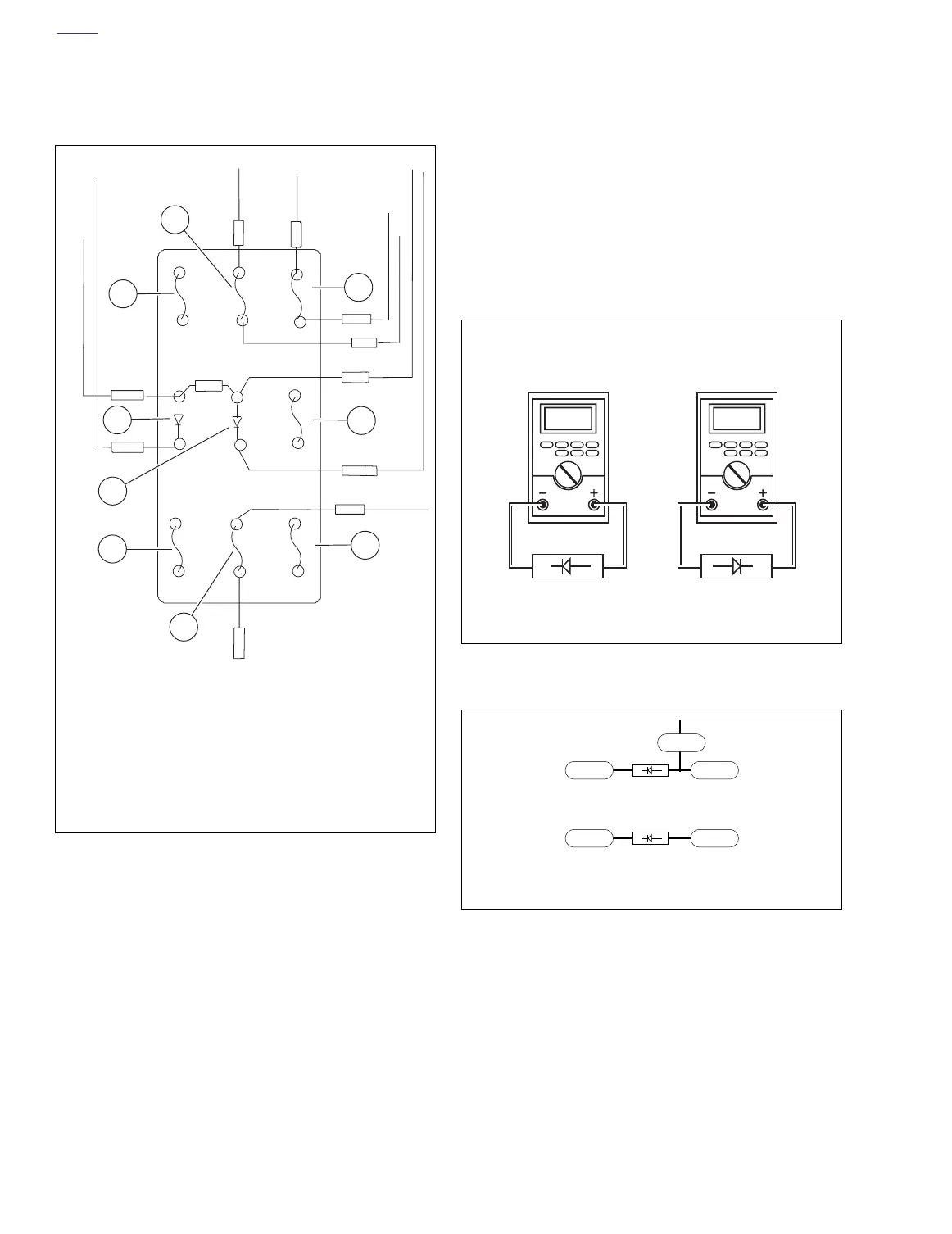
See Figure 7-39. The ignition fuse (5) is in the fuse block
under the seat. Always replace the ignition fuse with a 7.5
ampere fuse.
Diodes
See Figure 7-39. The fuse block contains two diodes, diode 2
(7) for the starter circuit and diode 1 (8) for the ignition circuit.
A diode acts as a one way switch which permits current flow
in one direction, but not in the other.
The circled numbers in the 7.11 STARTER/IGNITION INTER-
LOCK diagnostic ignition test flow charts correspond to the
following tests.
1. Check diode with an ohmmeter as shown in Figure 7-40.
2. Check diode polarity as shown in Figure 7-41.
Replace diodes as necessary.
Figure 7-39. Fuse Block [61]
[61]
TN/W
TN
R
R2
R/BK
15A
15A
15A
15A
TN/Y
TN/GR
O
7.5A
7.5A
7.5A
TN/Y
R/BK
GY
1
6
5
3
9
8
4
2
7
a0234x8x
1. Key switch
2. System
3. Spare 15A
4. Spare 7.5A
5. Ignition
6. Accessory
7. Diode 2 (starter circuit)
8. Diode 1 (ignition circuit)
9. Lights
Figure 7-40. Ohmmeter Diode Test
Figure 7-41. Diode Polarity
Continuity Infinite
ohms
a0235x7x
a0236x7x
TN TN/Y
Diode 1 polarity
TN/GN TN/Y
Diode 2 polarity
TN/W