7-42 2007 Buell P3: Electrical
HOME
ASSEMBLY/INSTALLATION
Depending on whether the rotor, the stator, or both the rotor
and stator were removed/disassembled, perform the applica-
ble procedures which follow:
1. See Figure 7-54. Feed stator wiring with attached grom-
met into open grommet hole in left crankcase half.
2. Apply a light coating of clean engine oil or chaincase
lubricant to grommet. Install grommet into hole in left
crankcase half.
IMPORTANT NOTE
Stator TORX screws contain a thread locking compound.
Do not reuse existing screws. Always use new screws
with the proper thread locking compound. Loss of torque
on TORX fasteners could result in alternator damage.
3. Position stator on left crankcase half. Secure stator using
four
new
TORX screws. Tighten screws to 30-40
in-lbs
(3-5 Nm).
4. Route stator wiring under starter, behind footpeg support
bracket and under seat. Cable strap connector [46]
halves together.
NOTE
Temporarily attach a thin flexible “feed” or mechanic’s wire to
the connector end of the stator wiring to assist in the routing
of the wiring.
5. Connect alternator stator wiring to voltage regulator con-
nector [46] located behind left footrest support.
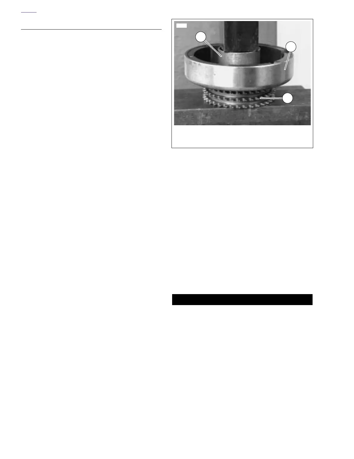
6. See Figure 7-55. Attach rotor to sprocket.
a. Position rotor on sprocket. Align holes in sprocket
with holes in rotor.
b. Apply a drop of Loctite 243 (blue) to threads of each
mounting bolt. Insert the eight mounting bolts
through rotor and start bolts into tapped holes in
sprocket.
c. Position a section of pipe with an inside diameter
larger than the sprocket mounting hub over center of
rotor. Press rotor onto sprocket. Tighten bolts to 90-
110
in-lbs
(10-12 Nm).
7. Install clutch assembly, primary chain and engine
sprocket/rotor assembly as a unit. See 6.4 PRIMARY
DRIVE/CLUTCH.
8. Install primary cover. See 6.2 PRIMARY CHAIN.
9. Connect negative battery cable to battery terminal.
Tighten fastener to 72-96
in-lbs
(8-11 Nm).
10. Test charging system. See 7.13 CHARGING SYSTEM.
11WARNING1WARNING
After installing seat, pull upward on front of seat to be
sure it is in locked position. While riding, a loose seat can
shift causing loss of control, which could result in death
or serious injury. (00070a)
11. Install seat. See 2.28 SEAT.
Figure 7-55. Pressing Rotor onto Sprocket
7806
1. Pipe section
2. Rotor
3. Sprocket
2
1
3