Model 190 Installation, Technical and Operation
8400-M022-O1 Rev J
13.3 Installing the BP190
1. Loosen the 4 Captive screws securing the rear housing to the
front housing assembly.
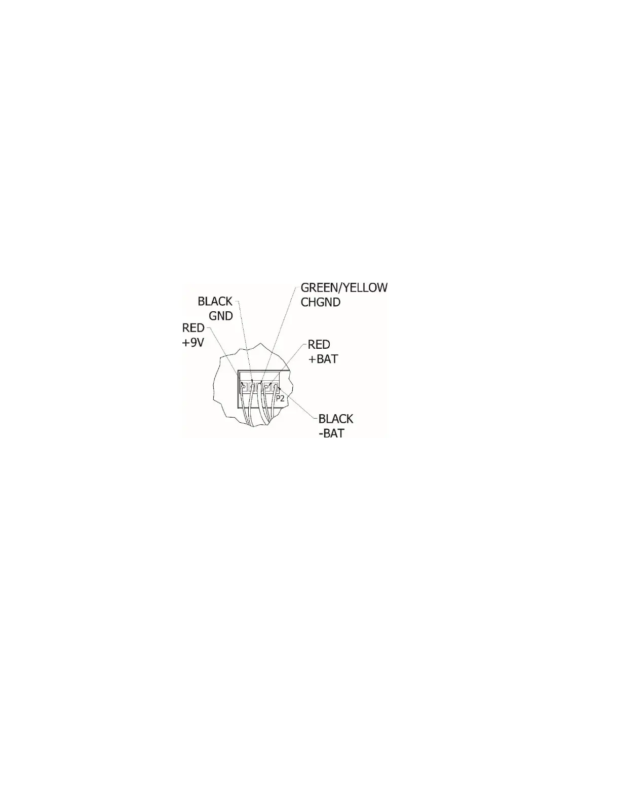
2. Remove 5-connector terminal block from P2 on 190 main board.
3. Referring to labels on circuit board for terminal connections,
connect each wire to terminal block.
4. To terminate a wire, loosen the screws in terminal block and
then insert the wire into terminal opening. Tighten screw to
secure the wire in place. Repeat procedure until both wires are
in place.
5. Insert two (2) cable ties through slots in the power supply cover
as shown on the next page.
NOTE: If your power supply cover does not have two (2) slots,
connect two (2) cable ties together and secure battery by sliding
cable tie behind power supply cover and over battery pack as
shown on the next page. Make sure the cable tie connections
are on the top of batteries and not the front of batteries.
6. Place battery pack on power supply cover.
7. Secure battery pack to power supply cover with cable ties.
8. Insert 5-connector terminal block removed in step 2 into P2 on
190 main board.
9. Make certain no cables or wires are exposed between the rear
housing and front housing assembly and then place the front
housing assembly onto the rear housing.
10. Secure by tightening the 4 Captive screws loosened earlier.
The indicator is ready for normal operations.
 Loading...