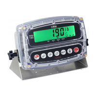
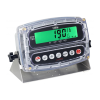
Model 190 Installation, Technical and Operation
8400-M022-O1 Rev J
Prty= (Option Card Parity Setting)
Press the TARE key to show the current setting. If the setting displayed
is 0, press the TARE key again to save it. Otherwise, use the Fn/ key
to toggle the parity setting to 0 (No Parity with 8 data bits) and then press
the TARE key to save it.
NOTE: The default parity is 0 (No Parity with 8 data bits) and should not
be changed.
Cont2= (Continuous Output on Option Card)
Press the TARE key to show the current setting. If the setting
displayed is no (no), press the TARE key again to save it. Otherwise,
use the Fn/ key to toggle the setting to no (No Continuous Output on
Option Card) and then press the TARE key to save it.
NOTE: The default continuous output is no (No Continuous Output on
Option Card) and should not be changed.
16.4 Ethernet Cable Installation
Connections to the 190 are by CAT 5 or equivalent cable. Consult your
network administrator for the proper procedure to terminate the cable.
After the cable has been terminated, plug the cable into the Ethernet port
on the 190-IP.
16.5 IP Address Setup
Before operation may begin the Ethernet Device Server must have an IP
Address. To facilitate control over the indicator on a network, we have
included the DeviceInstaller by Lantronix.
See the DeviceInstaller Users Guide (DeviceInstaller_UG.pdf) in the
Lantronix DeviceInstaller folder on the Model 190 Installation, Technical
and Operation Manual CD (8400-M022-O1) for details.
16.6 190-IP Operation
A client TCP connection to the 190-IP IP address at its listening port,
10001, can be used to send commands to the 190 indicator. A description
of the available commands are describe in section 9.11 ASCII Commands.
 Loading...