Model 190 Installation, Technical and Operation
8400-M022-O1 Rev J
3.3 Load Cell Connections
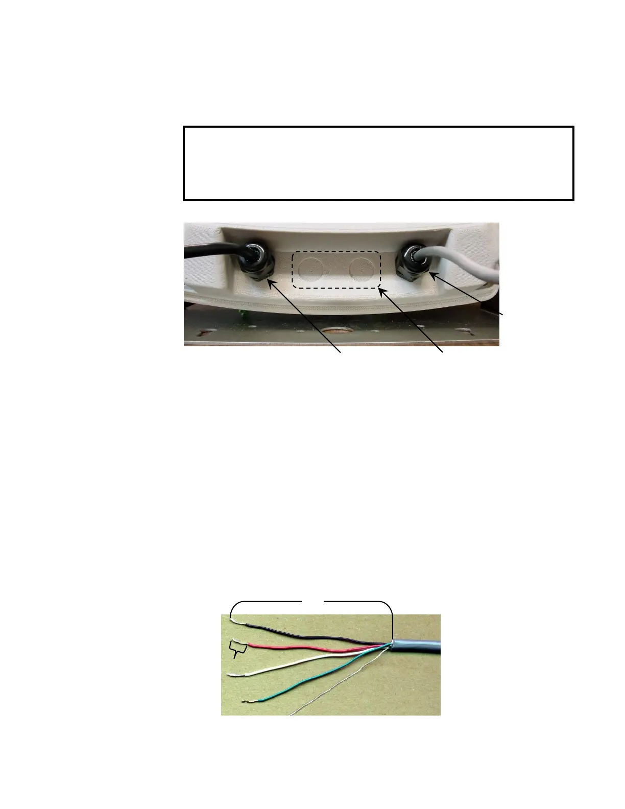
Figure No. 2
3.3.1. Loosen the 4 Captive screws securing the rear housing to the front
housing assembly.
3.3.2. Referring to Figure No. 2, choose a gland connector for the load cell
cable and loosen it.
3.3.3. Slip the single cable from the load cell or load cell junction box
through the gland connector and into the enclosure.
3.3.4. Referring to Figure No. 3, remove 3 inches of the outer insulation
jacket.
3.3.5. Next, remove 1/4 inch of insulation from each of the six wires and
shield (with sense leads) or four wires and shield (without sense
leads).
CAUTION! Disconnect any external load cell
power supply before connecting load cells to the
indicator. Failure to do so will result in permanent
damage to the indicator.
AC Power
100-240 VAC
0.4 Amp
I/O
(Serial, Isolated
Inputs/Outputs)
 Loading...