EasyManuals Logo

Cardinal 190 Series User Manual

Cardinal 190 Series
190 pages
To Next Page IconTo Next Page
To Previous Page IconTo Previous Page
Page #22 background imageLoading...
Page #22 background image
Model 190 Installation, Technical and Operation
8400-M022-O1 Rev J
Page 12
3.3.6. Remove the 7-connector terminal block connector from P5
on the 190 mainboard. Grasp the terminal block connector
and lift straight up away from the board.
3.3.7. Referring to the table below and the labels on the circuit
board for terminal connections, connect each wire to the
terminal block.
P5 Load Cell Wiring Table
P5 Board Label
Function
P5 Board Label
Function
+EXC
+ EXCITATION
-SIG
- SIGNAL
+SEN
+ SENSE
-SEN
- SENSE
+SIG
+ SIGNAL
-EXC
- EXCITATION
SHLD
SHIELD (Connect the load cell cable shield wire here).
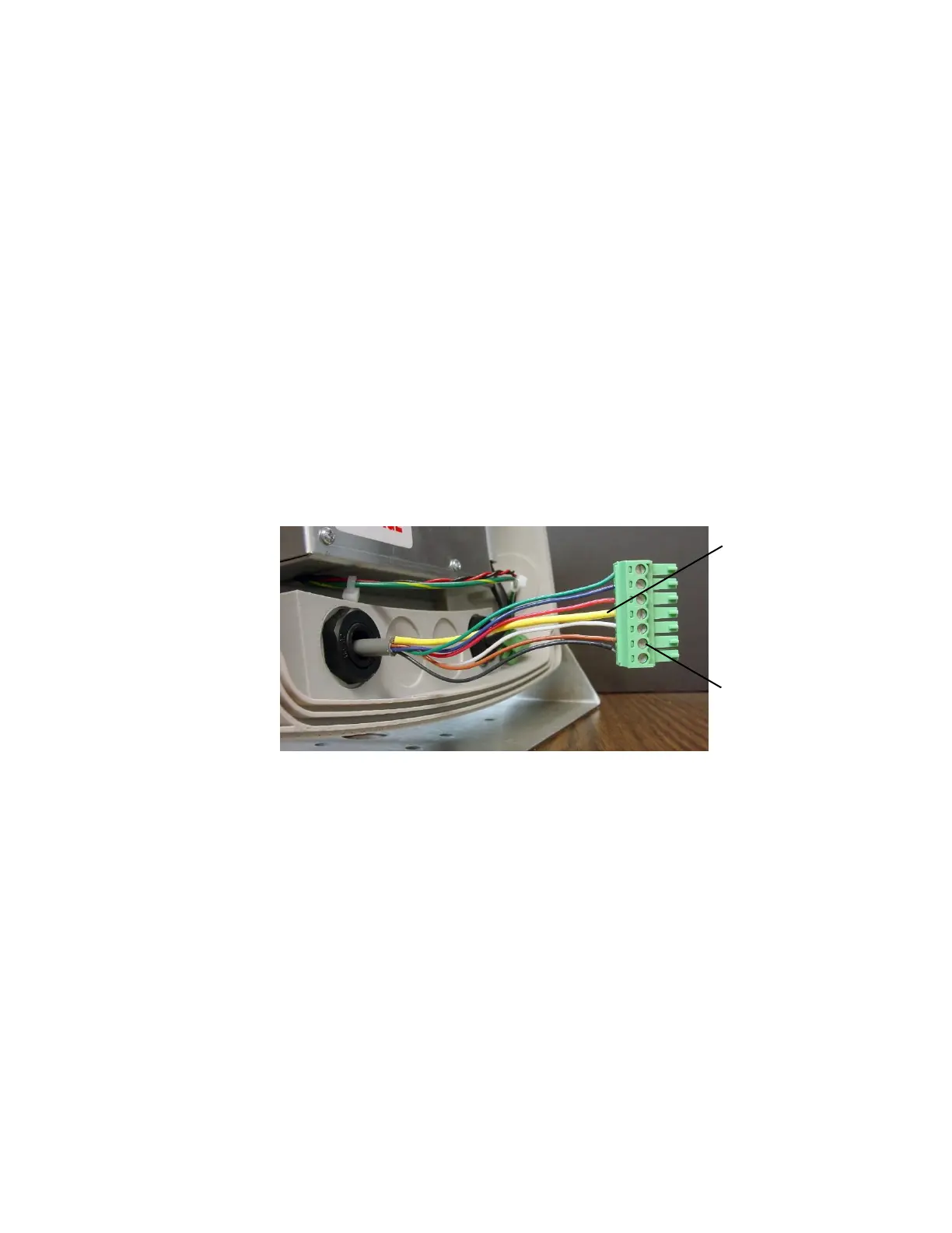
3.3.8. To terminate a wire, loosen the screws in the terminal block
and then insert the wire into the terminal opening. Tighten
the screw to secure the wire in place. See Figure No. 4.
Figure No. 4
3.3.9. Repeat the procedure until all wires are in place.
3.3.10. After all terminations have been made, remove the excess
cable from the enclosure.
Insert wire
and tighten
screw.
Load Cell
Shield Wire

Table of Contents

Questions and Answers:

Question and Answer IconNeed help?

Do you have a question about the Cardinal 190 Series and is the answer not in the manual?

Cardinal 190 Series Specifications

General IconGeneral
Touch TechnologyResistive
Display Size19 inches
Resolution1280 x 1024
Brightness250 nits
InterfaceUSB
Operating System CompatibilityWindows, Linux
Environmental RatingIP65
Active Area376.32 x 301.06 mm

Related product manuals