291
Configuring VLANs
Configuration Examples for Configuring VLANs
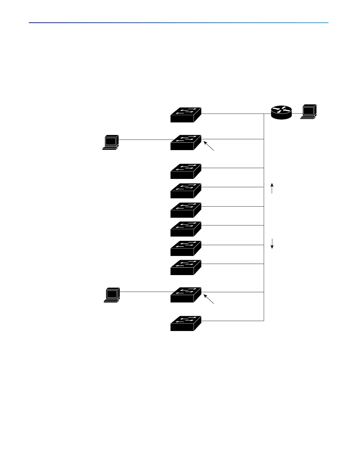
The Catalyst 6500 series Switch C and Switch J are secondary VMPS servers.
End stations are connected to the clients, Switch B and Switch I.
The database configuration file is stored on the TFTP server with the IP address 172.20.22.7.
Figure 32 Dynamic Port VLAN Membership Configuration
Configuring a VLAN: Example
This example shows how to create Ethernet VLAN 20, name it test20, and add it to the VLAN database:
Switch# configure terminal
Switch(config)# vlan 20
Switch(config-vlan)# name test20
Switch(config-vlan)# end
Primary VMPS
Server 1
Catalyst 6500 series
Secondary VMPS
Server 2
Catalyst 6500 series
Secondary VMPS
Server 3
172.20.26.150
172.20.26.151
Catalyst 6500 series switch A
172.20.26.152
Switch C
Ethernet segment
(Trunk link)
172.20.26.153
172.20.26.154
172.20.26.155
172.20.26.156
172.20.26.157
172.20.26.158
172.20.26.159
Client switch I
Client switch B
End
station 2
End
station 1
TFTP server
Dynamic-access port
Dynamic-access port
Switch J
Switch D
Switch E
Switch F
Switch G
Switch H
172.20.22.7
101363t
Trunk port
Trunk port
Router
 Loading...


