653
Cisco Systems, Inc. www.cisco.com
Configuring Static IP Unicast Routing
This chapter describes how to configure IP Version 4 (IPv4) static IP unicast routing on the switch. Static routing is
supported only on switched virtual interfaces (SVIs) and not on physical interfaces. The switch does not support routing
protocols.
Restrictions for Static IP Unicast Routing
By default, static IP routing is disabled on the switch.
Information About Configuring Static IP Unicast Routing
Note: When configuring routing parameters on the switch and to allocate system resources to maximize the number of
unicast routes allowed, use the sdm prefer lanbase-routing global configuration command to set the Switch Database
Management (SDM) feature to the routing template.
IP Routing
In some network environments, VLANs are associated with individual networks or subnetworks. In an IP network, each
subnetwork is mapped to an individual VLAN. Configuring VLANs helps control the size of the broadcast domain and
keeps local traffic local. However, network devices in different VLANs cannot communicate with one another without a
Layer 3 device to route traffic between the VLANs, referred to as inter-VLAN routing. You configure one or more routers
to route traffic to the appropriate destination VLAN.
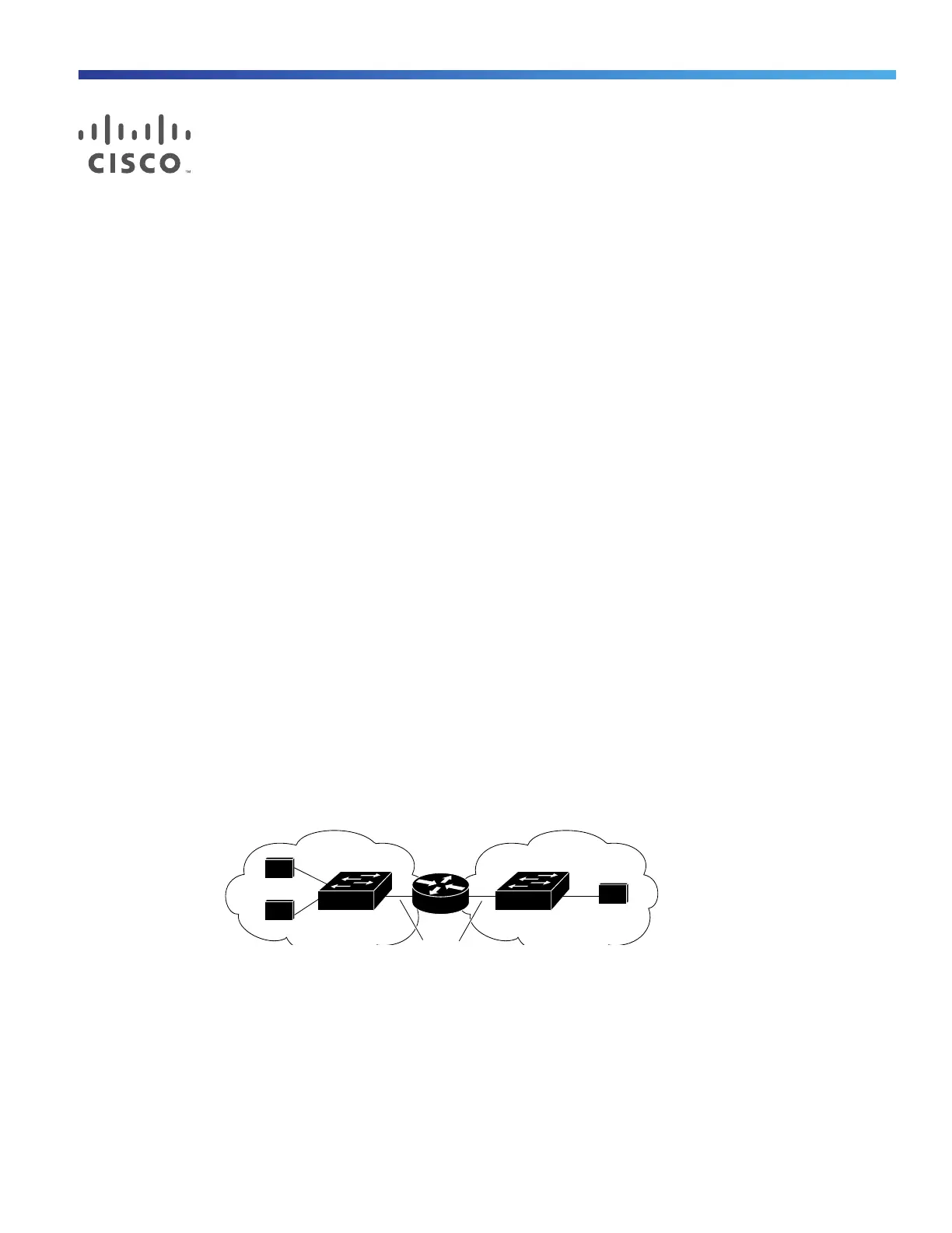
Figure 83 on page 653 shows a basic routing topology. Switch A is in VLAN 10, and Switch B is in VLAN 20. The router
has an interface in each VLAN.
Figure 83 Routing Topology Example
When Host A in VLAN 10 needs to communicate with Host B in VLAN 10, it sends a packet addressed to that host.
Switch A forwards the packet directly to Host B, without sending it to the router.
When Host A sends a packet to Host C in VLAN 20, Switch A forwards the packet to the router, which receives the traffic
on the VLAN 10 interface. The router uses the routing table to finds the correct outgoing interface, and forwards the
packet on the VLAN 20 interface to Switch B. Switch B receives the packet and forwards it to Host C.
When static routing is enabled on Switch A and B, the router device is no longer needed to route packets.
8071
A
B
C
Host
Host
Host
Switch A Switch B
VLAN 10 VLAN 20