Only use listed compression-type connectors when terminating the battery, battery return, and ground
conductors. Connectors must be suitable for copper conductors.
Note
When terminating power, return, and frame ground, do not use soldering lug connectors, screwless (push-in)
connectors, quick-connect connectors, or other friction-fit connectors.
Caution
If the system loses power or if both TCC2/TCC2P/TCC3 cards are reset, you must reset the ONS 15454 ETSI
clock. After powering down, the date defaults to January 1, 1970, 00:04:15. To reset the clock, see the “Turn
Up a Node” chapter in the Cisco ONS 15454 DWDM Configuration Guide.
Note
Procedure
Step 1 Verify that the MIC-A/P FMEC is installed in Slot 23 and the MIC-C/T/P FMEC is installed in Slot 24 of the
EFCA.
Step 2 Attach the connector on the end of the power cable to the power FMEC.
Step 3 Tighten the screws of the connector on the power cable.
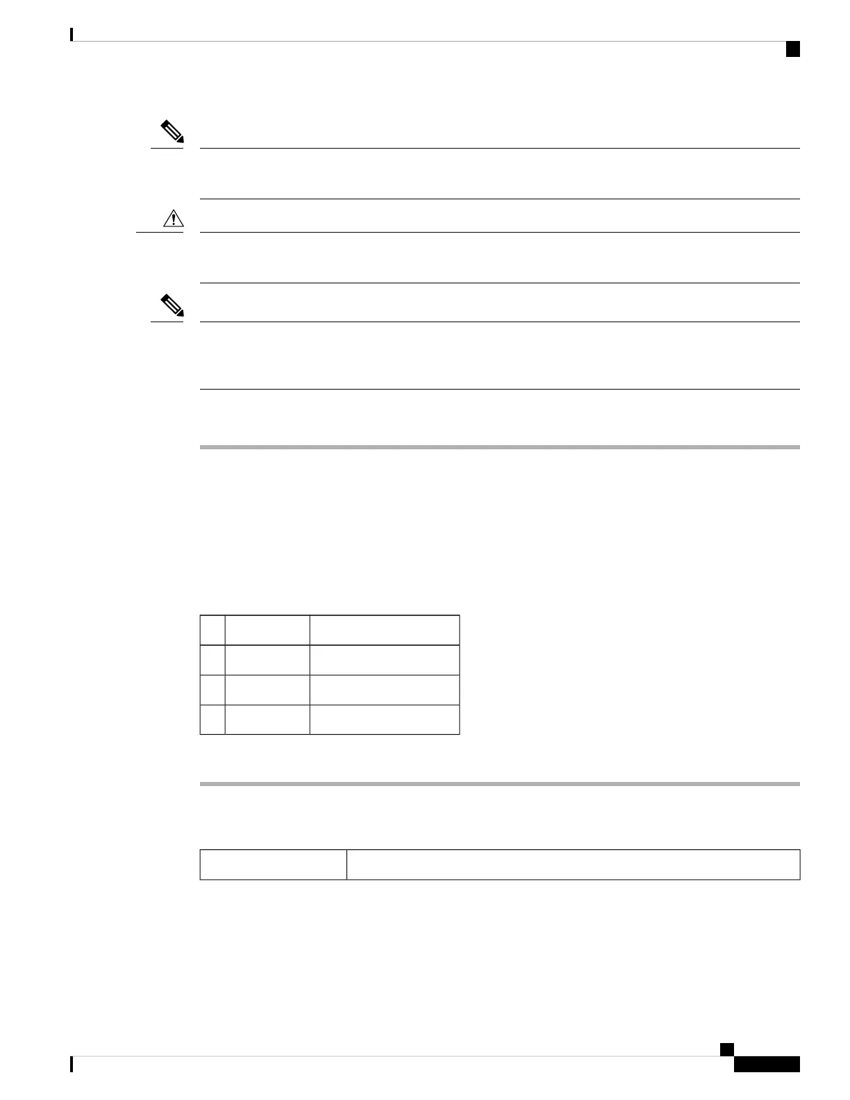
Step 4 Connect the power cable to the fuse panel or power source. Use the pin connections in the following table. If
the green-yellow cable is included in the power cable, it must be connected to ground.
Table 6: Pin Connection of the Power FMECs
Cable ColorFunctionPin
BlackBattery returnA1
Red–48 V batteryA2
Green with yellow stripesGroundA3
Step 5 Return to your originating procedure (NTP).
DLP-G18 Connect Office Power to the ONS 15454 ANSI
This task connects power to the ONS 15454 ANSI shelf.Purpose
Cisco ONS 15454 Hardware Installation Guide
71
Installing the ONS 15454 M12 (ANSI and ETSI) Shelf
DLP-G18 Connect Office Power to the ONS 15454 ANSI

 Loading...


