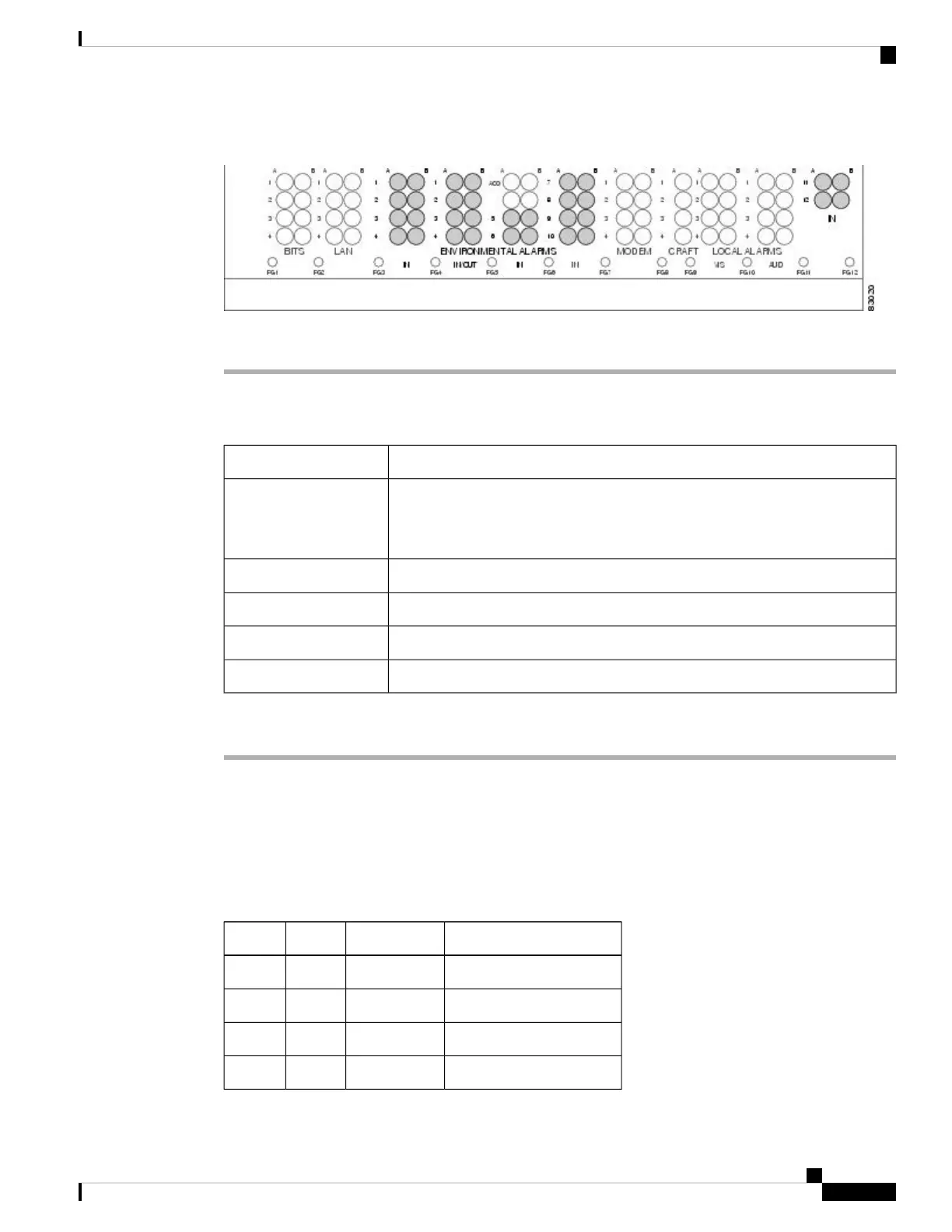
Figure 55: Highlighted Environmental Alarms
Step 2 Return to your originating procedure (NTP).
DLP-G24 Install Timing Wires on the Backplane (ANSI Only)
This task installs the BITS timing wires on the ONS 15454 ANSI backplane.Purpose
Wire wrapper
100-ohm shielded BITS clock cable pair #22 or #24 AWG (0.51 mm² or 0.64
mm²), twisted-pair T1-type
Tools/Equipment
NTP-G5 Remove the Backplane Covers (ANSI Only), on page 63Prerequisite Procedures
As neededRequired/As Needed
OnsiteOnsite/Remote
NoneSecurity Level
Procedure
Step 1 Using 100-ohm shielded BITS clock cable #22 or #24 AWG (0.51 mm² or 0.64 mm²), twisted-pair T1-type,
wrap the clock wires on the appropriate wire-wrap pins according to local site practice.
Ground the shield of the BITS input cable at the BITS end. For BITS output, wrap the ground shield of the
BITS cable to the frame ground pin (FG1) located beneath the column of BITS pins. Table 12: BITS External
Timing Pin Assignments, on page 98 lists the pin assignments for the BITS timing pin fields.
Table 18: External Timing Pin Assignments for BITS
FunctionCTC/TL1 NameTip/RingBITS Pin
Input from BITS device 1BITS-1ringA4
Input from BITS device 1BITS-1tipB4
Output to external device 1BITS-1ringA3
Output to external device 1BITS-1tipB3
Cisco ONS 15454 Hardware Installation Guide
109
Installing the ONS 15454 M12 (ANSI and ETSI) Shelf
DLP-G24 Install Timing Wires on the Backplane (ANSI Only)

 Loading...


