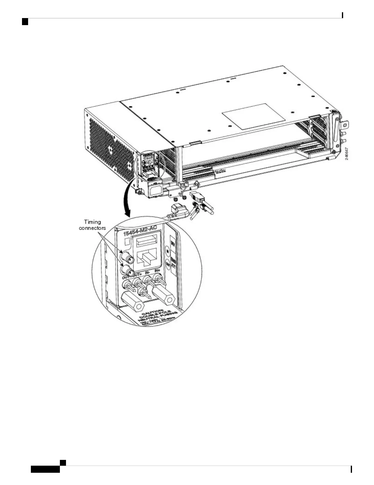
Figure 171: AC-2 Power Module ETSI BITS Connectors
Step 2 Using a coaxial cable with DIN 1.0/2.3 miniature coax connectors, connect the clock cable to the appropriate
connector in the Power Module.
Step 3 Gently push the cable with the DIN 1.0/2.3 miniature coax connector down until the cable connector slides
into the DIN 1.0/2.3 miniature coax connector on the Power Module with a click. The Power Module provides
DIN 1.0/2.3 miniature coax connectors that are used for timing input and output. The input connectors for
timing provide a 75-ohm termination. System cables that can convert timing clocks from 75 ohms to 100/120
ohms are available.
See ITU-T G.813 for rules about provisioning timing references.
Note
Step 4 Connect the other end of the cable to the external source of the timing.
Repeat step 3 for each cable that is needed.
Cisco ONS 15454 Hardware Installation Guide
260
Installing the ONS 15454 M2 Shelf
DLP-G293 Install Timing Wires in ONS 15454 M2 - ETSI

 Loading...


