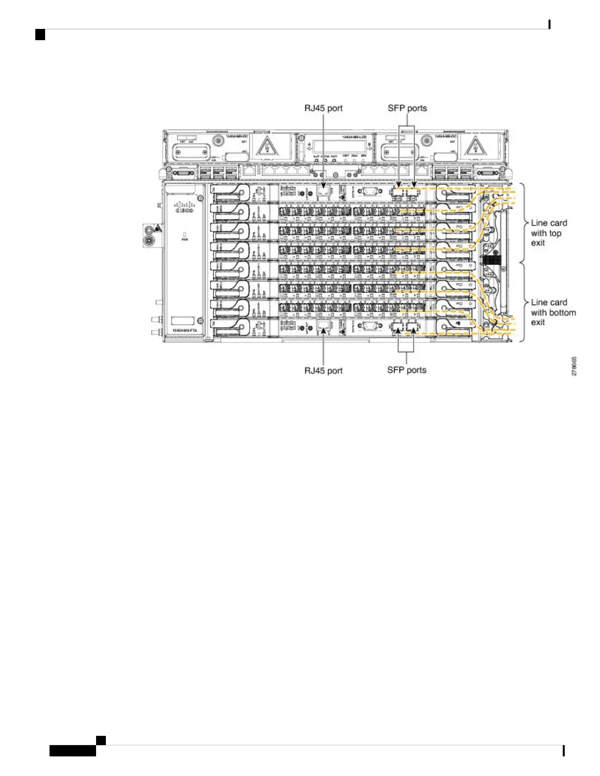
Figure 268: Cable Routing
b) Remove the front door and connect the copper cables to the SFP or RJ-45 ports of the cards.Do not route
the copper cables from the SFPs or RJ-45 ports through the fiber or cable module.
Step 4 To extract the power module, do the following:
a) Open the door of the chassis. See Diagram 2 of Figure 269: Sequence to Remove the Power Module, on
page 397.
b) Move the ECU cables away from the chassis. Ensure that the alarm cable with the plastic bend radius
controller is not moved. See Diagram 3 of Figure 269: Sequence to Remove the Power Module, on page
397.
c) Remove the power module. See Diagram 4 of Figure 269: Sequence to Remove the Power Module, on
page 397.
Cisco ONS 15454 Hardware Installation Guide
396
Installing the ONS 15454 M6 Shelf
DLP-G655 Route and Lock Cables

 Loading...


