Product Reference Guide 5
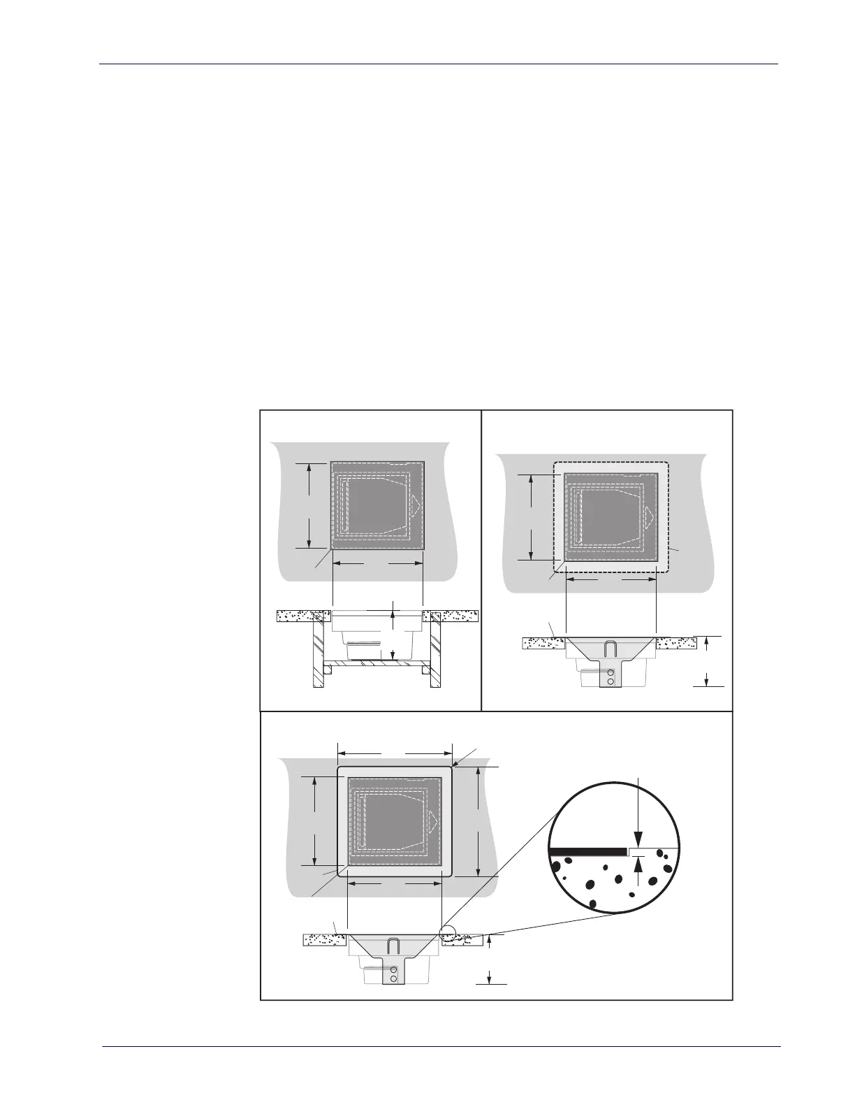
• Figure 3c provides dimensions if an adapter fixture holding the scanner
will be recessed to be flush
with the countertop.
3. Remove the Connector Cover, then connect and route the cables at the
sca
nner.
4. Seat the scanner or in the countertop opening (or adapter).
5. Switch the terminal OFF.
6. Connect the interface cable to the terminal.
7. If required, connect the scanner’s AC
Adapter to the AC outlet.
8. Switch the terminal ON.
9. Verify operation by scanning a few known-good bar
code labels. The
scanner should now be communicating the bar code data to the POS ter-
minal.
Figure 3. Countertop Cutouts
6.07"
(154.2mm)
6.07"
(154.2mm)
3.42"
(86.9mm)
Shelf Depth
a. Shelf installation b. Adapter w/flange above counter
c. Adapter w/flange recessed to be flush with counter
6.26"
(159mm)
3.47"
(88.1mm)
Rim rests on top of counter
6.26"
(159mm)
Rim is flush with counter
Cut hole
6.26"
(159mm)
3.52"
(89.4mm)
6.26"
(159mm)
7.91"
(201mm)
Routing is 0.050" (1.27mm) deep
Radius 0.21" (5.3mm) x4
Cut hole
Rim of
adapter
Cut hole
Routed ledge
for rim
7.40"
(188mm)
 Loading...