Chapter 28: Control Surface Reference 207
Main Unit Back Panel
Power Switch
The Power switch applies power to the D-Show Main Unit.
AC Power Connector
The AC Power connector accepts a standard AC power cable.
The D-Show Main Unit is auto-power selecting (100V to
240V) and automatically works with a standard modular
power cord when connected to an AC receptacle in any coun-
try.
FOH Link Connector
The FOH Link connector accepts the FOH Link cable supplied
with the FOH Rack. This cable provides all the data and audio
connections between the D-Show Console and the FOH Rack.
VGA Port
The VGA port accepts a standard VGA display connector for
the D-Show system monitor. A 15-inch XVGA display with a
minimum resolution of 1024 x 768 is recommended.
USB Port
The USB port on the back panel of the Main Unit is a USB 1.1
port. This port supports iLoks, USB key disks, and USB key-
boards.
Footswitch Ports 1 & 2
The Footswitch ports on the back panel of the Main Unit are
standard 1/4-inch TRS connectors. The Footswitch function is
set in the Interaction tab of the Options page.
Console Link Connectors (Sidecar 1–3, 4–6)
The Console Link connectors use standard AES/EBU digital
XLR cables (not microphone cables) to connect the Main Unit
to Sidecars. Sidecars 1–3 are daisy-chained and connected to
the first connector.
Sidecars 4–6 are daisy-chained and connected to the second
connector.
Light Ports (2)
The two powered light ports support optional 3-pin XLR con-
sole lights.
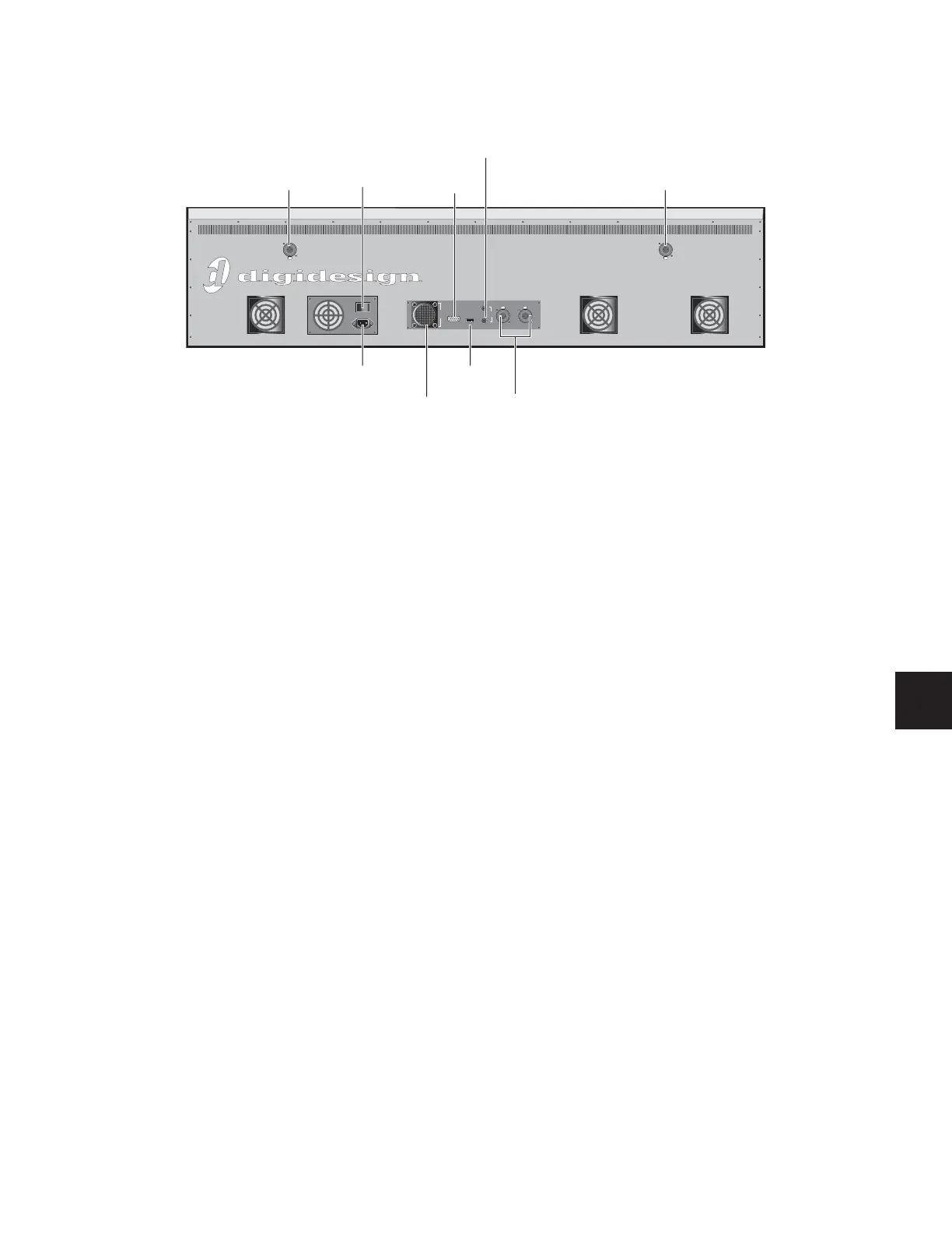
Figure 17. Main Unit back panel
IO
FOH Link
To Rack
Footswitch
Console Link
Sidecar 4-6
Console Link
Sidecar 1-3
VGA
USB
1
2
Light Light
Power
switch
FOH
Link
connector
USB
port
VGA
port
Footswitch
ports
AC power
connector
Console
Link
connectors
Light
port
Light
port