APPENDIX C
Door Safety Switch
Above Ground Model 200iX/250iX Motorcycle Dynamometer Installation Guide
C-6
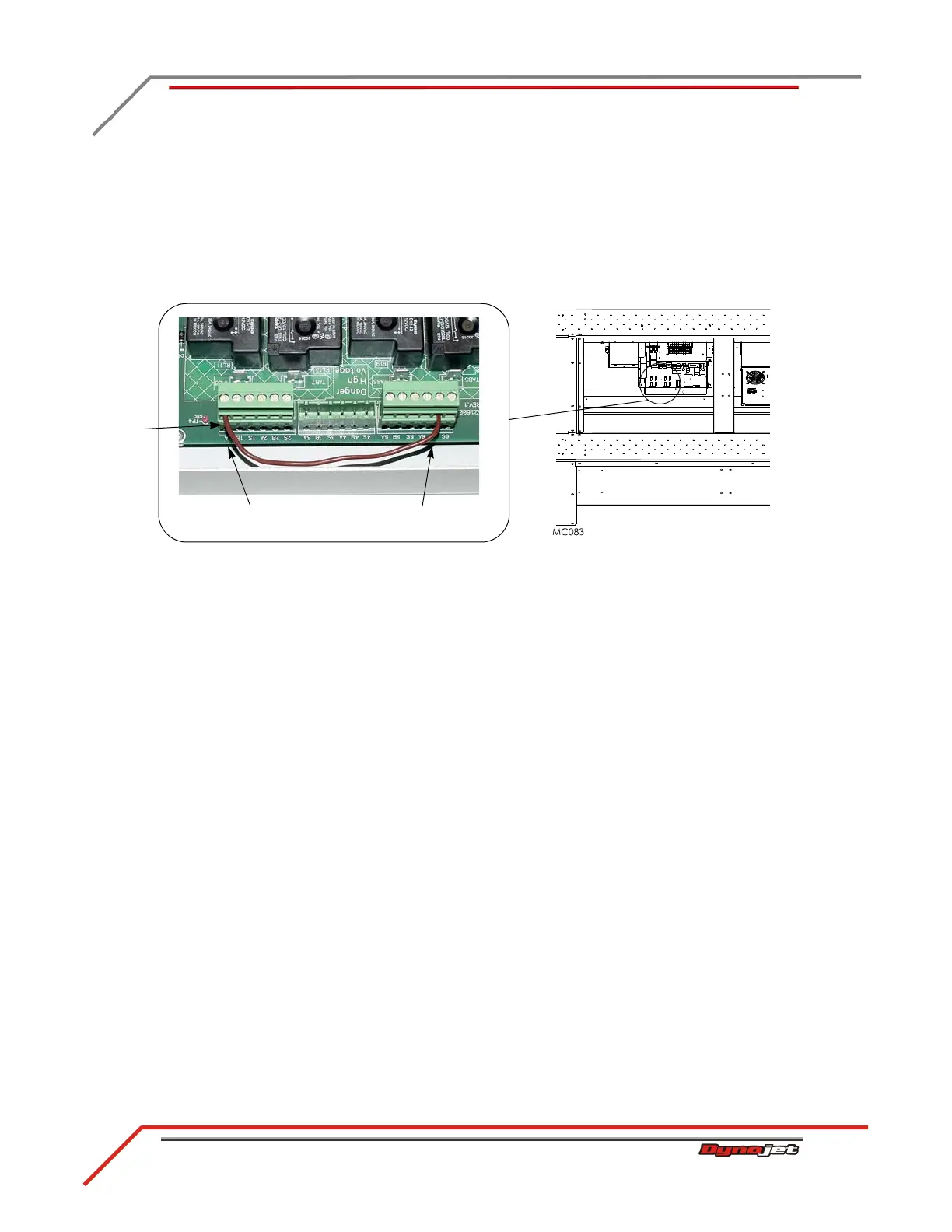
4 Loosen the screws that hold the jumper wires in place and remove the wire.
5 Route the black and yellow wire from the safety switch through the dyno.
Make sure the switch will not get caught in any moving components or chafed on
any edges.
6 Attach the yellow wire to the 1A position on the J2 connector.
7 Attach the black wire to the 6B position on the J4 connector.
Figure C-5: Wire the Safety Switch
8 Replace the CPI cover using the screws removed earlier.
9 The door safety switch needs to be mounted at the entry of the dyno room.
10 Plug the dyno into the power outlet.
11 Turn on the main breaker inside the CPI door.
12 Open the door safety switch by allowing the plunger to extend.
The air brake should be applied holding the drum and the status light on the
control panel will be flashing.
13 Depress the safety switch and the air brake will release and the status light will be
on steady.
black wire to 6B on
J4 connector
yellow wire to 1A
on J2 connector
remove
jumper
wire