2-29
INSTALLATION
iX Drum Module Installation
Version 2 Above Ground Model 200iX/250iX Motorcycle Dynamometer Installation Guide
INSTALLING THE BULKHEADS
You will need the following parts:
• 21200022 Middle Bulkhead
• 21200024 Front Bulkhead
• 21600012 Toe Kick Bracket
• 36468100 Nut, 1/4-20, Nylock (5)
• 36561045 Screw, 1/4-20 x 5/8", Ph, Torx (16)
• 61300007 Monitor Support Brace
• 76950053 Cable, Fan Power Extension
1 Place the monitor support brace on the five studs on the front bulkhead.
2 Secure the brace to the studs using five 1/4-20 nylock nuts.
3 Secure the front bulkhead to the dyno frame using four 1/4-20 x 5/8-inch pan-
head torx screws.
4 Secure the middle bulkhead to the dyno frame using five 1/4-20 x 5/8-inch pan-
head torx screws.
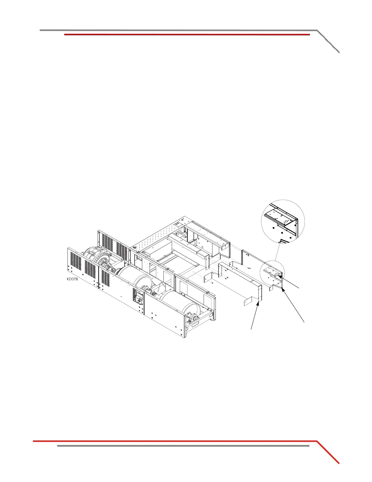
Figure 2-24: Securing the Front and Middle Bulkheads
middle bulkhead
front bulkhead
monitor support
brace