CHAPTER 2
Control Panel and Cable
Above Ground Model 200iX/250iX Motorcycle Dynamometer Installation Guide
2-50
CONTROL PANEL AND CABLE
Use the following instructions to route the control panel cable and install the control
panel to the support arm or monitor tray.
You will need the following parts:
• 36540643 Screw, 8-32 x 3/8", Ph, Phil (13)
• 43428232 Cable Clamp (7)
• 61329000 Control Pod Spindle
• 66117001 Control Panel Assembly
1 Remove the control panel rear cover.
1a Remove the two nuts from the top of the cover and set aside.
1b Remove the screw on the top of the cover and set aside.
1c Remove the screw on the side of the cover and set aside.
1d Remove the four screws on the back of the cover and set aside.
1e Remove the control panel rear cover and set aside.
Figure 2-42: Remove the Control Panel Rear Cover
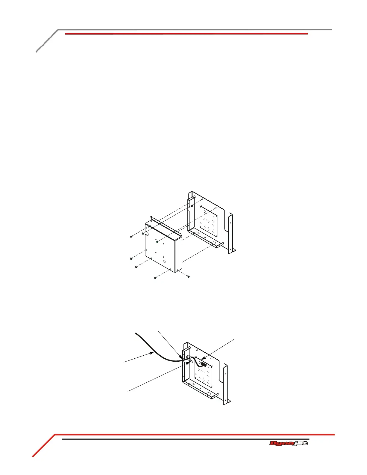
2 Route the control panel cable through the access hole on the side of the control
panel box and through the cable tie.
3 Attach the control panel cable to the Button board.
Figure 2-43: Attach the Control Panel Cable to the Button Board
control panel cable with
cable harness wrap
access hole
cable tie
button board