Above Ground Model 200iX/250iX Motorcycle Dynamometer Installation Guide
3-4
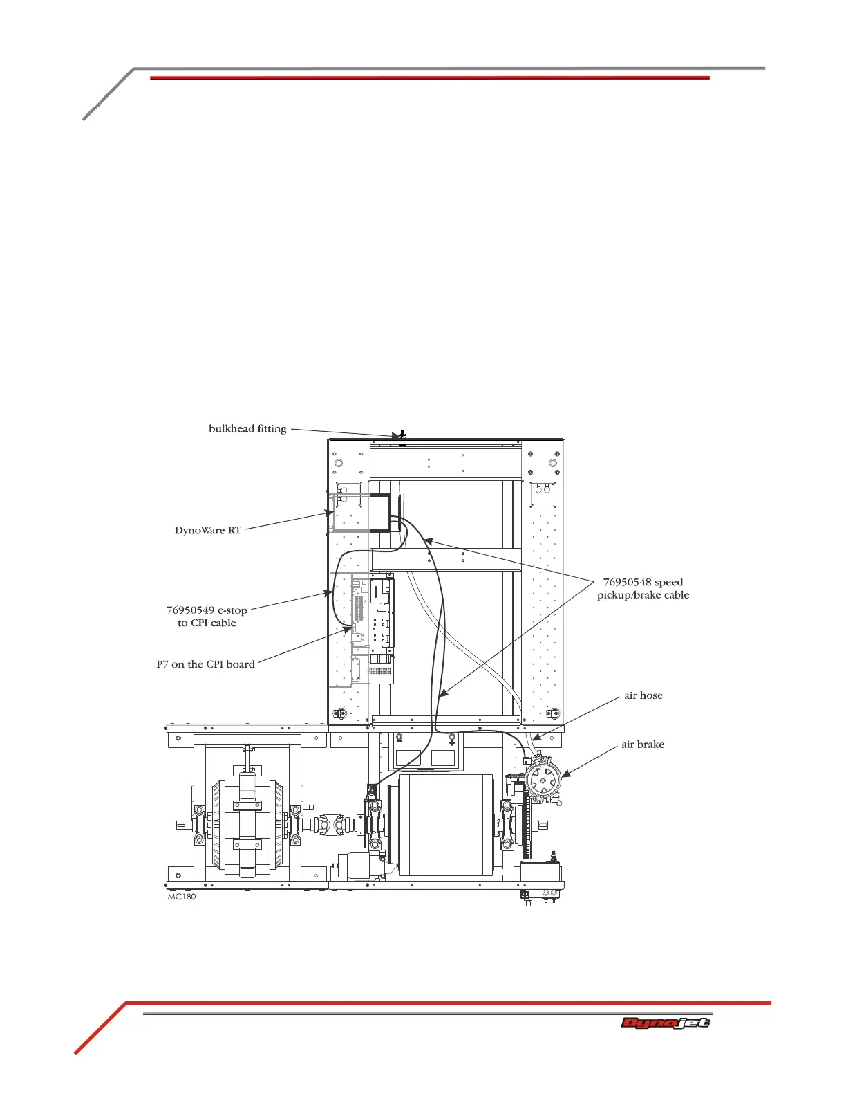
ROUTING THE AIR BRAKE CABLES AND AIR HOSE
1 Route the white two-pin connector from the speed pickup/brake cable to the
solenoid leads on the brake assembly.
2 Attach the two-pin connector to the brake solenoid leads.
3 Route the E-stop cable from the rear of the DynoWare RT module to P7 on the CPI
front panel.
4 Attach the two-pin connector to the DynoWare RT module.
5 Attach the flat four-pin connector to P7 on the CPI board.
6 Route the air hose from the air brake through the access hole in the drum module
upright, under the carriage frame brace, and connect to the bulkhead fitting at the
front of the dyno.
You will need to provide an air hose nipple (1/4-inch NPT) to connect your clean,
dry shop air supply (60 psi, 415 kilopascal, max constant line pressure) to the
dynamometer.
Figure 3-3: Route the Air Brake Cables and Air Hose