2-49
INSTALLATION
Monitor Support and Tray
Version 2 Above Ground Model 200iX/250iX Motorcycle Dynamometer Installation Guide
MONITOR SUPPORT AND TRAY
You will need the following parts:
• 26215520 Washer, 1/8", Poly, for Monitor Support (3)
• 35521420 Cap Plug, for Monitor Support (4)
• 36582034 Bolt, 3/8-16 x 1.25", Button-head, Flange (4)
• 61329100P Monitor Arm (2)
• 61329101P Monitor Tray
• 61329500P Monitor Support
1 Secure the monitor support to the dyno using four 3/8-16 x 1.25-inch button-head
flange bolts.
Note: Make sure the fan arm mount is sandwiched in between the dyno panel and
the monitor support base.
2 Place a 1/8-inch thick poly washer around the pin on the lower monitor arm.
3 Insert the pin on the lower monitor arm into the monitor support.
4 Place a 1/8-inch thick poly washer around the pin on the upper monitor arm.
5 Insert the pin on the upper monitor arm into the lower blower arm.
6 Place a 1/8-inch thick poly washer around the pin on the monitor tray.
7 Insert the pin on the monitor tray into the upper blower arm.
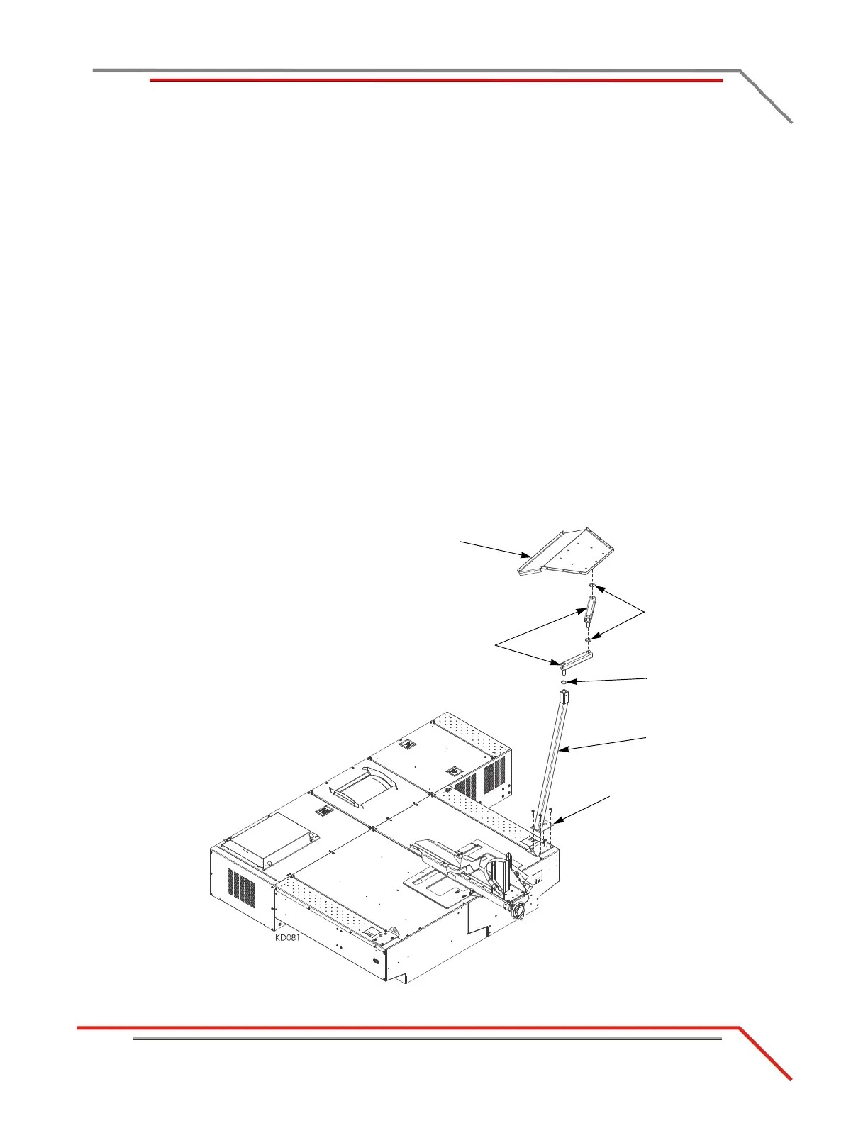
Figure 2-41: Installing the Monitor Support and Tray
monitor
support
fan arm mount under
monitor support
washer
tray
arms
washers