CHAPTER 2
iX Drum Module Installation
Above Ground Model 200iX/250iX Motorcycle Dynamometer Installation Guide
2-28
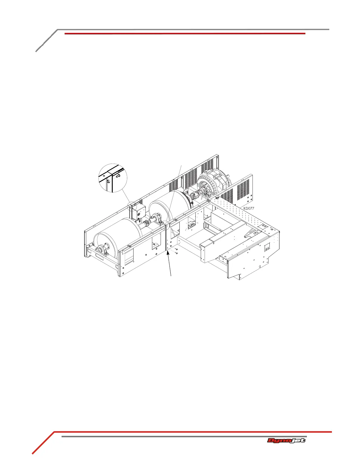
11 Secure the connector plate on either side of the drum module to the dyno frame
using the screws removed earlier.
12 Verify the panels on the drum module and the dyno line up. These covers must be
flush and parallel. If these covers are not flush, place shims between the floor and
the drum module or the dyno until they are flush.
13 Once aligned, tighten all screws.
14 Secure the side panels on the drum module to the panels on the dyno using one
1/4-20 x 5/8-inch screw.
15 Replace the existing set screws on the driveline assembly with the thread-lock set
screws provided.
16 Tighten the driveline set screws.
Figure 2-23: Securing the Drum Module to the Dyno
secure connector plate
not visible from
this view