APPENDIX E
Above Ground iXW Upgrade Installation
Above Ground Model 200iX/250iX Motorcycle Dynamometer Installation Guide
E-12
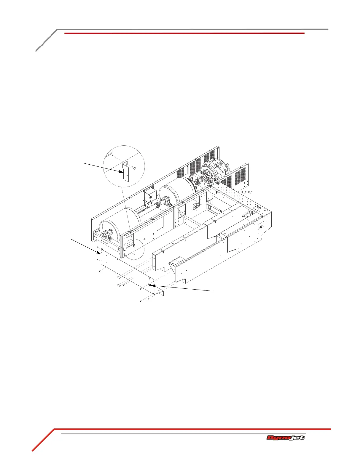
5 Remove the existing 3/8-inch screw from the drum module and secure the toe
kick bracket to the drum module.
6 Attach the blower power extension cable to the existing blower cable,
disconnected earlier, by matching up the colors.
7 Attach the blower power extension cable to the fan socket.
• Connect the brown wire to N
• Connect the blue wire to L
• Connect the green/yellow wire to ground
8 Secure the dyno side cover to the bulkheads using the eleven screws removed
earlier.
Figure E-6: Securing the Toe Kick Bracket and Dyno Side Cover
dyno side cover
fan socket
toe kick bracket