2-3
INSTALLATION
Unpacking and Inspecting the Dyno
Version 2 Above Ground Model 200iX/250iX Motorcycle Dynamometer Installation Guide
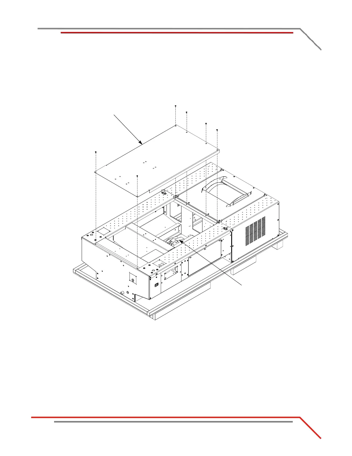
6 Remove the six 1/4-inch screws securing the center panel on the dyno and remove
the center panel.
Note: Dynojet recommends using a T30 Torx driver (Snap-On PFTx30E) to
remove the 1/4-inch screws.
7 Remove the tire stop, tire lock, and hardware from the middle of the dyno.
Figure 2-2: Remove the Center Panel
center panel
tire stop and tire lock
in middle