2-33
INSTALLATION
Cable Routing
Version 2 Above Ground Model 200iX/250iX Motorcycle Dynamometer Installation Guide
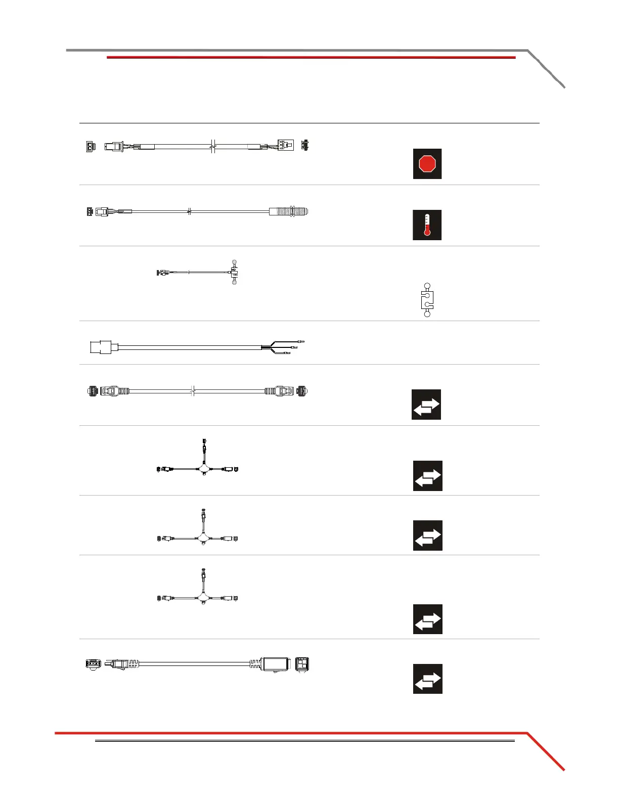
K - 76950549 e-stop to CPI cable connects the DynoWare RT to P7 on the front of the
CPI panel
L - 76950569 IR temp sensor cable connects to the temp sensor cable to the eddy current
brake driver
M - 76950573 load cell cable connects the load cell to the eddy current brake
driver
*optional accessory
N - 76950646 AFR power cable connects the CPI to the air fuel module
*optional accessory
O - 76950680 CAN powersports cable connects Dynojet Powersports products to the
DynoWare RT (PCV, OBD2)
P - 76950791 CAN control cable, 15' connects the eddy current brake driver to the
DynoWare RT using the CAN adapter cable or CAN
network cable chain
Q - 76950798 CAN dyno user cable, 15' connects the POD intercept to the DynoWare RT
using the CAN adapter cable
R - 76950798 CAN dyno user cable, 15' connects the air fuel module to the DynoWare RT
using the CAN adapter cable or CAN network cable
chain
*optional accessory
S - 76950807 CAN control cable, adapter, 2' connects the DynoWare RT to the CAN control and
CAN dyno user cables
cable brief routing description