9 Interface module MCB-HK-SWD for circuit-breakers and residual current circuit-breakers
9. 4 In s t a l l a t i o n
SmartWire-DT module IP20 01/20 MN05006001Z-EN www.eaton.com 215
9.4 Installation
MCB-HK-SWD interface modules are designed for installation on DIN-rails.
They must be installed in a vertical position.
Procedure
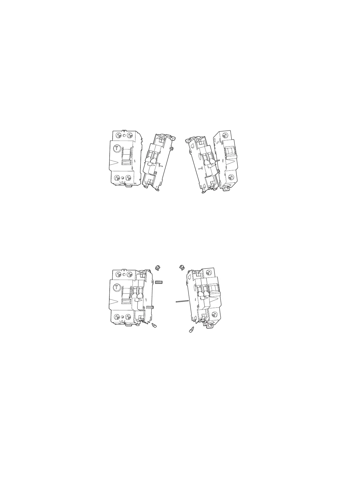
▶ Push the centering pin (red) through the circuit-breaker and connect the
interface module to the circuit-breaker.
Figure 77: Connecting the interface module to the circuit-breaker
▶ Remove any unneeded auxiliary contact parts.
Depending on whether the auxiliary contact is connected to a residual
current circuit-breaker, a miniature circuit-breaker, or a residual current
operated circuit-breaker with overcurrent protection, the connection pins
or locking mechanisms will need to be removed from the side not con-
nected to the circuit-breaker so that there will be a flat surface.
Figure 78: Removing the connection pins
▶ Use the SmartWire-DT socket to connect the 8-conductor SmartWire-DT
cable to the top or bottom of the device.
Due to EMC reasons, the SmartWire-DT socket strip that remains
unused must be covered with included accessory SWD4-…. Failure to do
so may result in communication problems and in SmartWire-DT modules
being damaged and ruined.
 Loading...


