2 I/O modules EU5E-SWD…
2.12 Analog module EU5E-SWD-4AX
50 SmartWire-DT module IP20 01/20 MN05006001Z-EN www.eaton.com
2.12.4 Installation
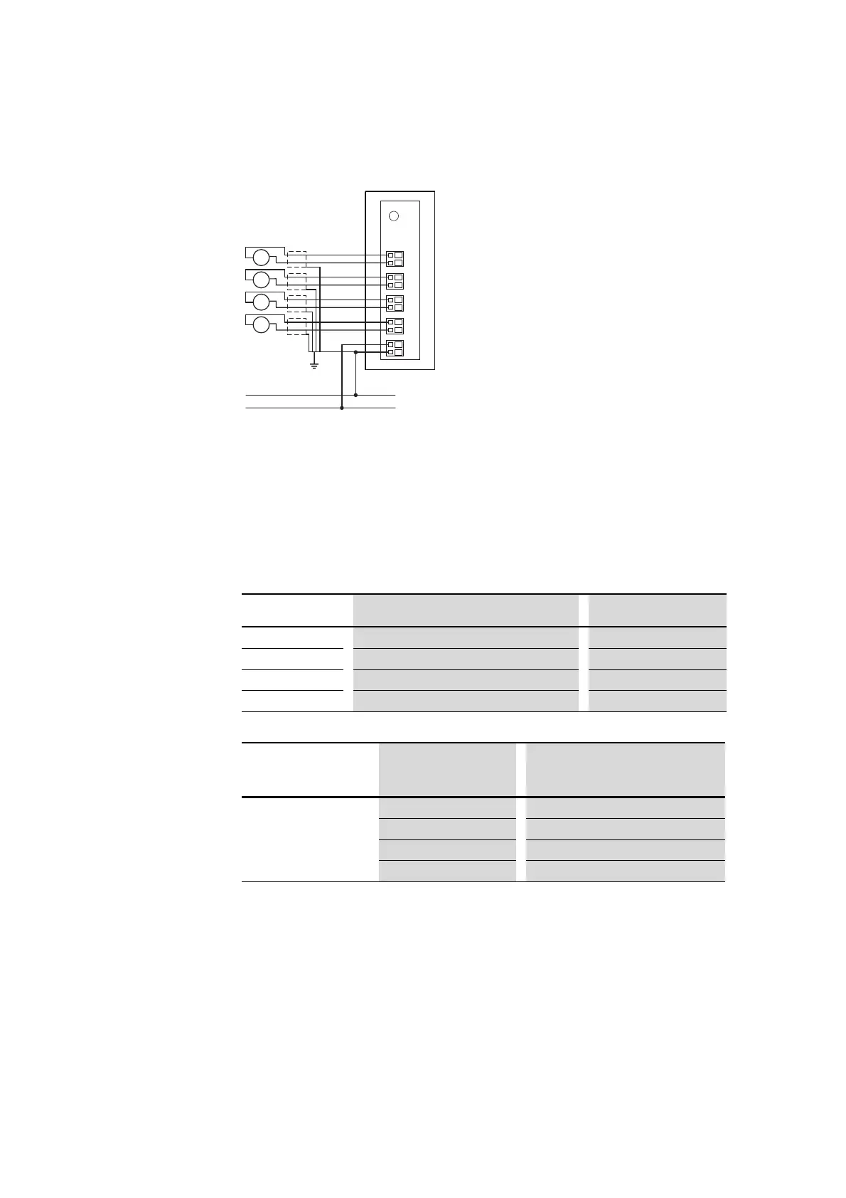
Figure 21: Connecting inputs and power supply
▶ Connect the analog sensors to the corresponding inputs I0 to I3.
▶ Connect the 24 V power supply for the card.
2.12.5 Parameterization
With the programming system’s control configurator, users can define the
sensor model, measured value refresh rate and averaging.
This setting applies for all channels.
The specified value is the refresh time to the SmartWire-DT coordinator. An
averaging function, which smooths input signal fluctuations can be activated
separately.
2.12.6 Fieldbus-specific characteristics
Field bus CANopen
U/I
0 V
24 V DC
+
U/I
+
U/I
+
U/I
+
24 V
0 V
I0–
I2+
I1–
I1+
I0+
I2–
I3+
I3–
Parameter Setting options Basic Setting
Sensor type I0 Voltage (0 - 10 V), current (0 - 20 mA) Voltage (0 - 10 V)
Sensor type I1
Voltage (0 - 10 V), current (0 - 20 mA) Voltage (0 - 10 V)
Sensor type I2
Voltage (0 - -10 V), current (0 - 20 mA) Voltage (0 - 10 V)
Sensor type I3
Voltage (0 - 10 V), current (0 - 20 mA) Voltage (0 - 10 V)
Parameter
Reading update Averaging
On (default) Off
Reading refresh rate 20 ms 1 –
100 ms (default setting) 5 measurement cycles
200 ms 10 measurement cycles
500 ms 25 measurement cycles

 Loading...


