2 I/O modules EU5E-SWD…
2.14 Analog modules EU5E-SWD-4PT and EU5E-SWD-4PT-2
60 SmartWire-DT module IP20 01/20 MN05006001Z-EN www.eaton.com
2.14.4 Installation
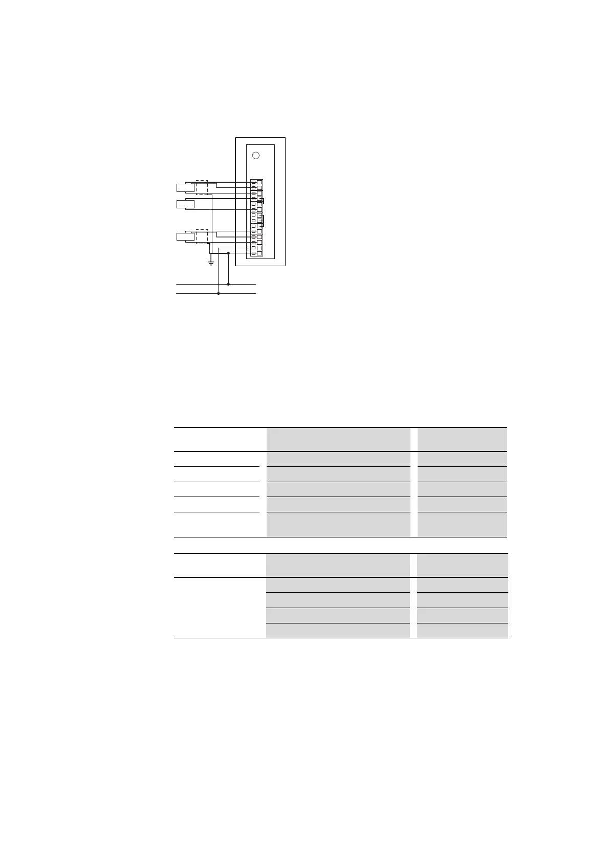
Figure 25: Connecting inputs and supply of module EU5E-SWD-4PT/...4PT-2
▶ Connect the sensors to the corresponding inputs I0 to I3.
▶ Connect the 24 V power supply for the card.
2.14.5 Parameterization
With the programming system’s control configurator, users can define the
sensor model, measured value refresh rate and analog input representation.
This setting applies to all analog inputs. The specified value is the refresh
time for the SmartWire-DT network. An averaging function, which smooths
input signal fluctuations, is associated with this setting.
0 V
24 V DC
RTD
RTD
24 V
0 V
RTD
B0
a0
A0
B1
a1
A1
B2
a2
A2
B3
a3
A3
Parameter Setting options Basic Setting
Sensor type 1 Not used, PT100, PT1000, Ni1000 Not Used
Sensor type 2
Not used, PT100, PT1000, Ni1000 Not Used
Sensor type 3
Not used, PT100, PT1000, Ni1000 Not Used
Sensor type 4
Not used, PT100, PT1000, Ni1000 Not Used
Look
Degrees Celsius, degrees Fahrenheit, nonlinear
value
Degrees Celsius
Parameter
Reading refresh rate Averaging
Reading refresh rate/aver-
aging
0.25 s (default setting) –
1s 4 measurement cycles
2.5 s 10 measurement cycles
10 s 40 measurement cycles
 Loading...


