4 PKE-SWD-32, interface for motor-starter combination with PKE PKE12/32
4.9 Programming
SmartWire-DT module IP20 01/20 MN05006001Z-EN www.eaton.com 109
4.9 Programming
4.9.1 PKE-SWD-32 cyclical data
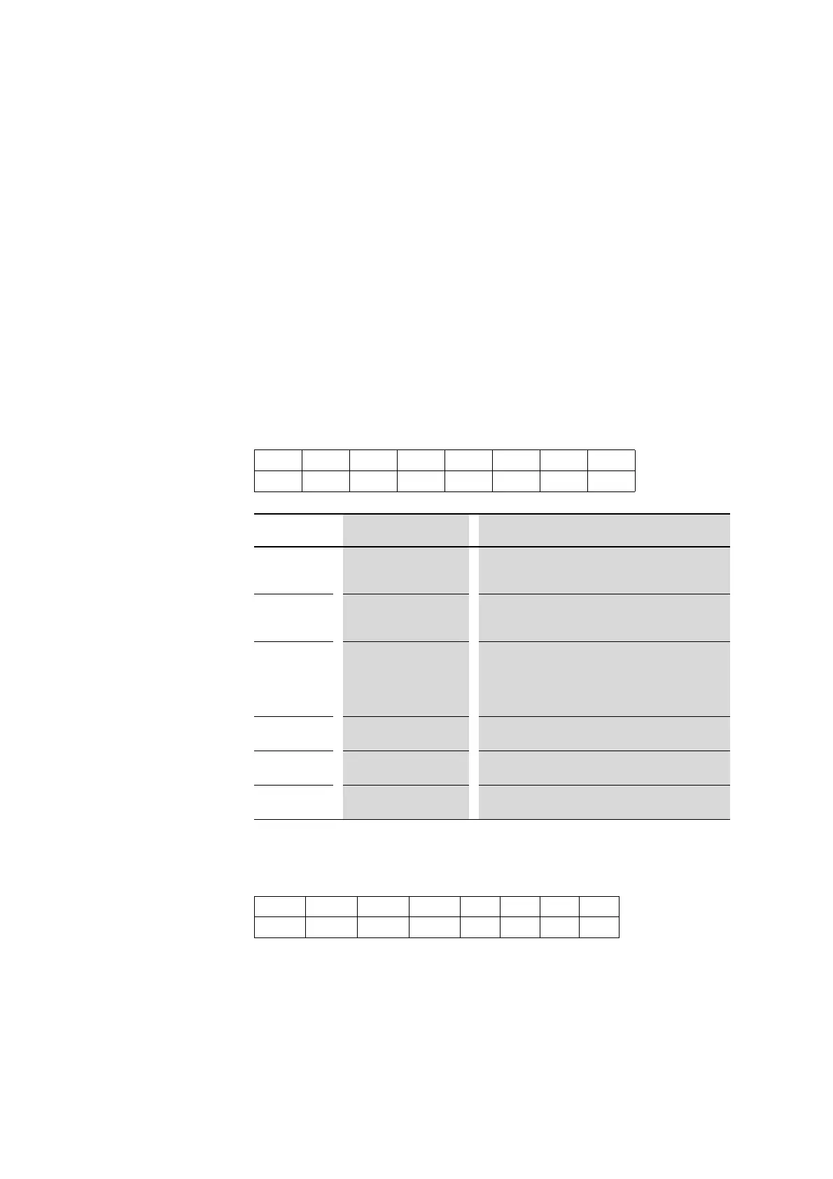
The PKE-SWD-32 has a maximum of five input bytes and one output byte.
4.9.1.1 Input points
Byte 0:
Status information: DILM, PKE, PKE-SWD-32
Byte 1:
Set value I
r
, trip reasons, acknowledge signal
→
The number of cyclical input bytes can be adjusted by means of
different data profiles of the module (→ Section 4.9.3, "Data
profiles", page 120).
76543210
SUBST PRSNT – DIAG A2 A1 P C
Data bit
Designation Description
0 C = Contactor Contactor state Contactor
0: contactor not tripped
1: contactor tripped
1
Stat. PKE status
0: PKE switched of/tripped
1: PKE Powered up
2-3
A1, A2 Position of 1-0-A switch
00: Incorrect position for longer than 4 seconds
01: Position A (Switching command via SWD)
10: Position 0 (Contactor OFF)
11: Position 1 (Contactor ON)
4
DIAG 0: No diagnostic alarm
1: Module signals diagnostics
6
PRSNT 0: Module not available
1: Module available
7
SUBST 0: Configured module present
1: Universal module M22-SWD-NOP(C) present
76543210
ACKR TRIPR TRIPR TRIPR Ir Ir Ir Ir
 Loading...


