2 I/O modules EU5E-SWD…
2.5 Installation
24 SmartWire-DT module IP20 01/20 MN05006001Z-EN www.eaton.com
▶ Lay the AC supply voltage cables in separate cable ducts to those used
for signal or data cables.
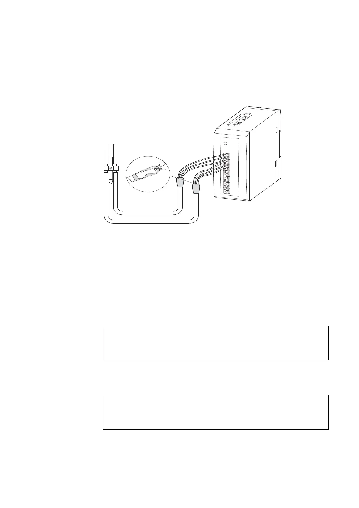
▶ Lay signal and data cables as close as possible to the earthed surfaces of
the switchgear cabinet.
Figure 7: Wiring of analog sensors/actuators
2.5.4 Commissioning
Having connected all SmartWire-DT modules to the SmartWire-DT network,
press the configuration button on the gateway, which then automatically
assigns addresses to the modules.
During address assignment, the modules’ SmartWire-DT diagnostics LED
flashes. After address assignment, the LED is continuous lit green.
2.5.5 Exchange of modules
After replacement of the modules and connection of the voltage the configu-
ration button must be pressed. When this is done, the new module will be
assigned an address.
ACHTUNG
Switch off the entire SmartWire-DT system before replacing
SmartWire-DT input/output modules.
ACHTUNG
The order of the SmartWire-DT units must not be altered.
 Loading...


