2 I/O modules EU5E-SWD…
2.10 Digital module EU5E-SWD-4D2R
SmartWire-DT module IP20 01/20 MN05006001Z-EN www.eaton.com 43
2.10.4 Installation
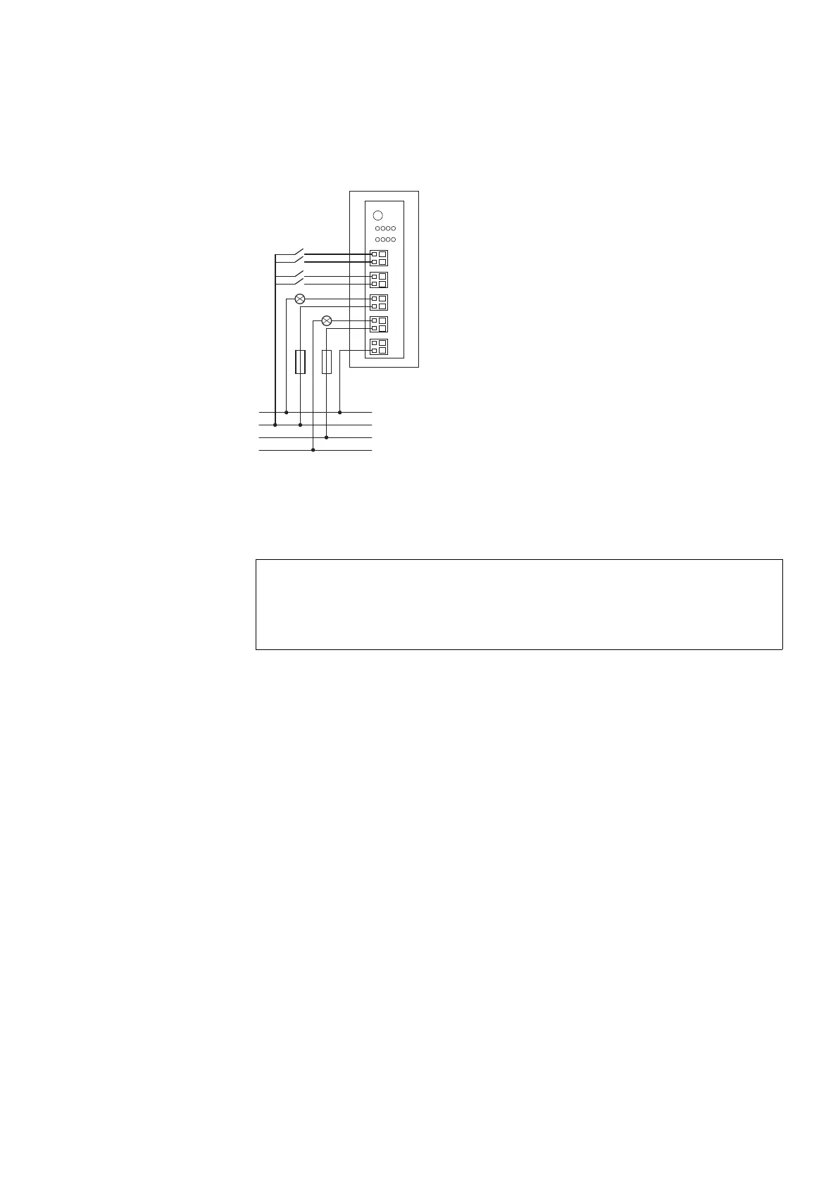
Figure 17: Connecting the inputs/outputs of module EU5E-SWD-4D2R
▶ Connect the sensors to the corresponding inputs I0 to I3.
▶ Connect the reference potential 0 V DC to connection 0V.
▶ Wire the first relay output to Q1 and the second to Q2.
2.10.5 Parameterization
Depending on the coordinator being used, the module's parameters will
need to be configured in the programming system or in the SWD-Assist plan-
ning and commissioning program.
2.10.6 Fieldbus-specific characteristics
Fieldbus EtherCAT
Please note the general information for configuring parameters
→ Chapter 12 “Using SWD modules with the EtherCAT field bus”, page
247, particularly
→ Section , „Device options“, page 247..
2.10.7 Programming
The module has two input bytes and one output byte at its disposal.
2.10.7.1 Input points
Byte 0:
ACHTUNG
The relays Q1 and Q2 can be subjected to a rated operational
current of up to AC3, -15 A at 250 V. They must be protected
with a 4 A fuse.
0 V
24 V DC
L
N
4 A
4 A
10
Q
12
3
0
I
I1
I0
I3
I2
0 V
1
2
Q1
1
2
Q0
1
2

 Loading...


