11 Interface for NZM compact circuit-breakers
11.6 Parameterization
234 SmartWire-DT module IP20 01/20 MN05006001Z-EN www.eaton.com
11.6 Parameterization
Depending on the coordinator being used, the module's parameters will
need to be configured in the programming system or in the SWD-Assist plan-
ning and commissioning program.
11.7 Fieldbus-specific characteristics
Field bus Ethercat
Please note the general information for configuring parameters
→ Chapter 12 “Using SWD modules with the EtherCAT field bus”, page
247.
11.8 Programming
11.8.1 Cyclic data
11.8.1.1 Data profiles
Table 62: Data profile NZM-XSWD-704
From byte 1, the data structure of profile 1 and 2 complies with the LVSG
(Low Voltage Switchgear) profile of the PNO (PROFIBUS User Organization).
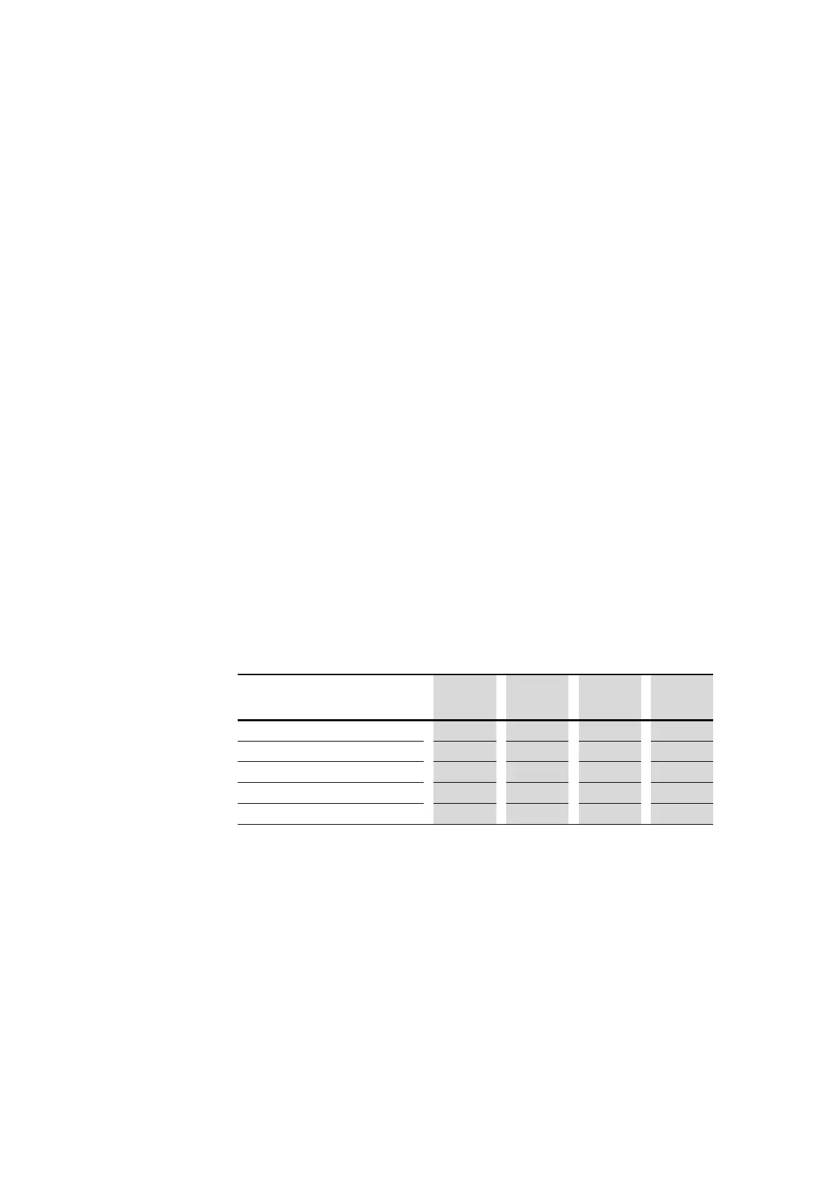
Table 63: Overview of the data profiles of the NZM-XSWD-704
→
Four different profiles are made available for the cyclical data.
Data profile 1 only contains the digital status data of the circuit-
breaker, whilst the currents and the energy values are contained
in the remaining profiles.
Profile 4 contains all the information of the NZM.
Profile 1 Profile 2
(default)
Profile 3 Profile 4
Bytes total 3 11 15 31
Digital status data
X X X X
Currents
– X X X
Energy values
– – X X
Set values and circuit-breaker data
– – – X
Note: The NZM starts the current measurement at a current greater than about 5% of the circuit-breaker’s rated
current; at smaller currents it outputs a zero value. A 400 A breaker, for example, supplies values at currents above
about 20 A. This threshold value is independent of the rotary encoder setting.
→
Data bytes that are not transferred cyclically in certain profiles
can still be read as acyclical data objects
(→ Chapter 11 “Interface for NZM compact circuit-breakers”,
page 246).

 Loading...


