2 I/O modules EU5E-SWD…
2.12 Analog module EU5E-SWD-4AX
SmartWire-DT module IP20 01/20 MN05006001Z-EN www.eaton.com 49
2.12 Analog module EU5E-SWD-4AX
2.12.1 INTRODUCTION
SmartWire-DT I/O module EU5E-SWD-4AX provides four analog inputs, to
which voltage (0 – 10 V) or current sensors (0 – 20 mA) can be connected.
The SmartWire-DT diagnostic LED is used to signal the network's/module's
status.
2.12.2 Surface mounting
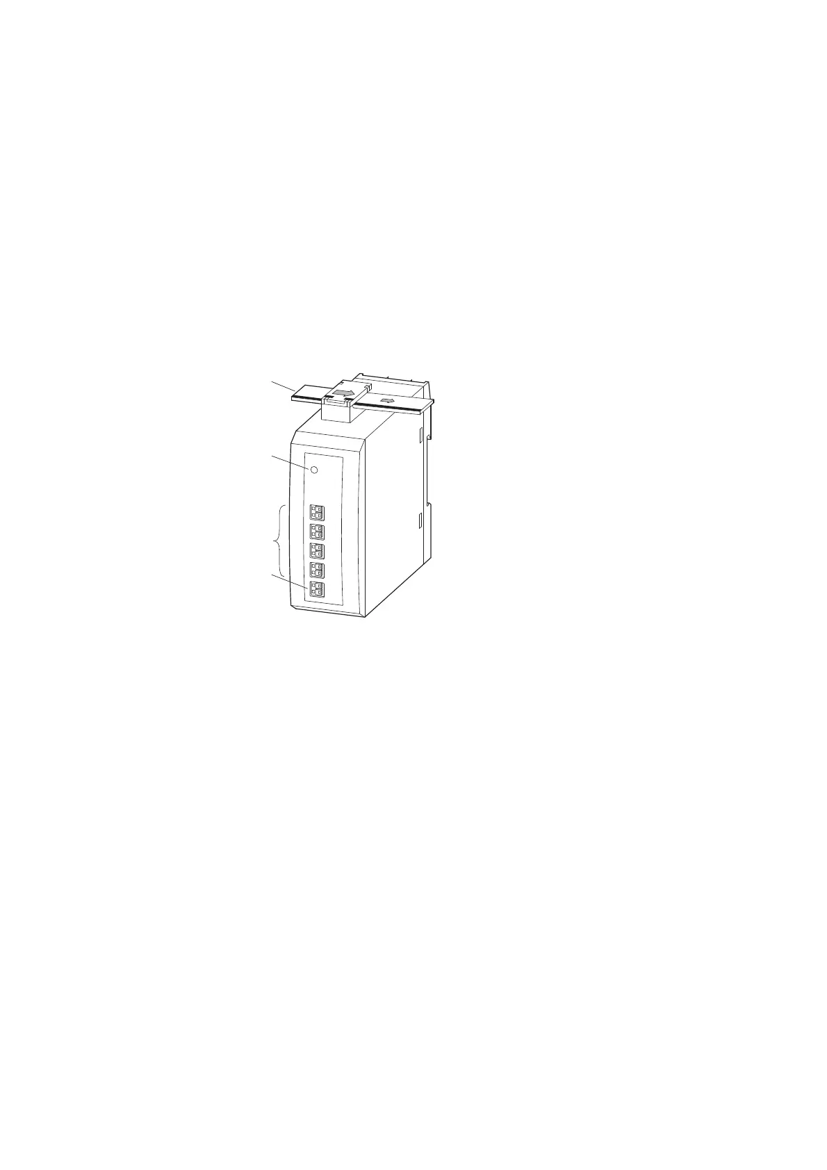
Figure 20: Layout of module EU5E-SWD-4AX
2.12.3 Engineering
The analog inputs can be connected as two-wire connections. The inputs are
electrically isolated from the SmartWire-DT network but not from each other.
The signal range (voltage 0–10 V, current 0–20 mA) can be separately set for
each of the four analog inputs. The selection is made in the programming
system’s control configurator. The resolution is 12 Bit.
a SmartWire-DT cable with external device plug
b SmartWire-DT diagnostics LED
c Inputs I0 – I3
d 0-V-24-V connection supply
→
All 0 V connections (I
x
- ; x = 0, 1, 2, 3) are connected with each
other and with the module’s 0 V supply.

 Loading...


