2 I/O modules EU5E-SWD…
2.13 Analog module EU5E-SWD-2A2A
54 SmartWire-DT module IP20 01/20 MN05006001Z-EN www.eaton.com
2.13 Analog module EU5E-SWD-2A2A
2.13.1 INTRODUCTION
SmartWire-DT I/O module EU5E-SWD-2A2A provides two analog inputs and
two analog outputs for current.
Current (0 – 20 mA) or voltage (0 – 10 V) sensors or actuators can be con-
nected to the inputs/outputs.
The resolution is 12 Bit.
The SmartWire-DT diagnostic LED is used to signal the network's/module's
status.
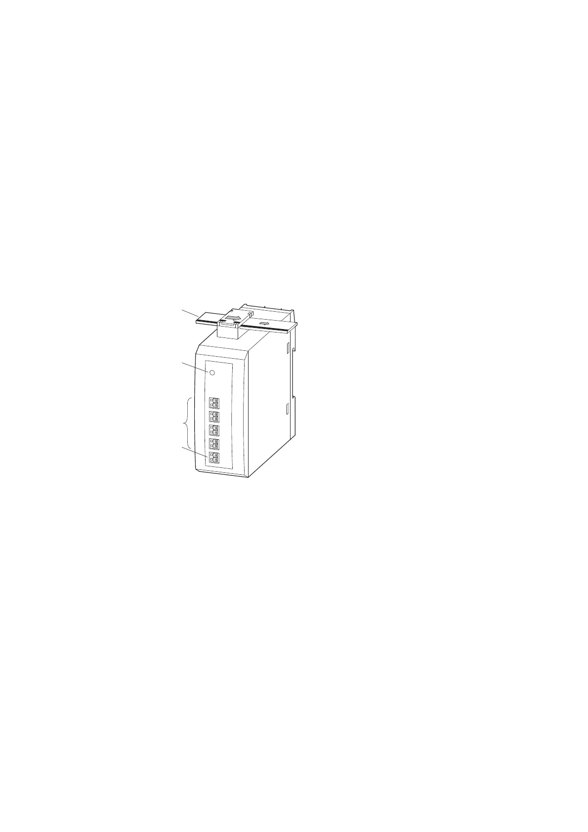
2.13.2 Surface mounting
Figure 22: Layout of module EU5E-SWD-2A2A
2.13.3 Engineering
The signal range (voltage 0 – 10 V, current 0 – 20 mA) can be separately set
for each input and output. The selection is made in the programming sys-
tem’s control configurator.
The inputs/outputs are electrically isolated from the SmartWire-DT network
but not from each other.
The resolution is 12 Bit.
The outputs are short-circuit proof.
a SmartWire-DT cable with external device plug
b SmartWire-DT diagnostics LED
c Input IA0, IA1, output QA0, QA1
d 0-V-24-V connection supply
→
All 0 V connections (I
x
- , Q
x
- ; x = 0, 1) are connected with each
other and with the module’s 0 V supply.

 Loading...


