10 SmartWire-DT universal module M22-SWD-NOP and M22-SWD-NOP-C
10.6 Programming
224 SmartWire-DT module IP20 01/20 MN05006001Z-EN www.eaton.com
After replacement of the modules and connection of the voltage the configu-
ration button must be pressed. When this is done, the new module will be
assigned an address.
10.5.2 Device status
The individual SmartWire-DT universal modules indicate their device status
with the aid of a diagnostic LED.
Table 61: Diagnostic messages of the SmartWire-DT status LED
10.6 Programming
The universal modules contain specific information that the programming
system processes. The meaning and scope are described in the following.
The universal modules always have an input byte.
The length of the input and output bytes depends on the replaced function
element.
Bit 7 (SUBST) in the first input byte is set to indicate that a universal module
is fitted in place of the software-configured module.All process data of the
configured module is zero.
Designation Color State Message
SWD Green Continuous light Device is operating fault-free.
flashing (1 Hz) • addressing process in progress
• after gateway power On
• after actuation of the configuration button on the gateway
• Module not in current configuration
• invalid type
flashing (3 Hz) Device reports a diagnostics. (see section “Programming”, subsec-
tion “Diagnostics”).
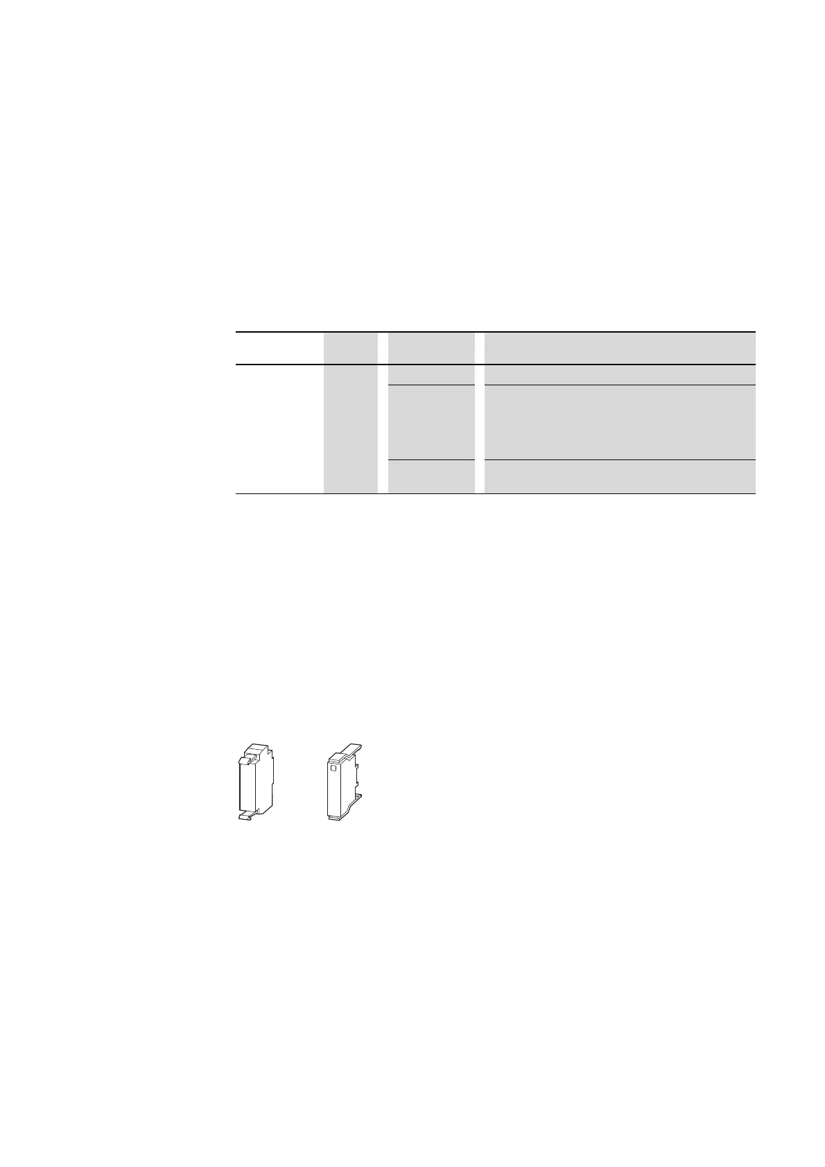
Figure 85: M22-SWD-NOP, M22-SWD-NOPC
 Loading...


