3 Switching on DIL-SWD-32-001, DIL-SWD-32-002 contactors
3.3 Engineering
72 SmartWire-DT module IP20 01/20 MN05006001Z-EN www.eaton.com
The switch positions are as follows:
• 1 - Contactor ON
• 0 - Contactor OFF
• A - Switching command via SmartWire-DT
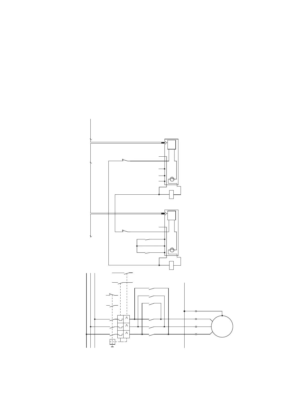
Figure 29: Circuit diagram of the reversing starter in combination with DILM12-XEV
→
Use of the 1-0-A switch for the electrical switching on or off of
the contactor is ensured only when the SmartWire-DT module
for DILM is supplied via the SmartWire-DT connecting cable.
-Q11 -Q12
21
22
-Q11
X3 X4
8
21
22
8
SmartWire-DT
A1
A2
-Q12
X1 X0 X2 X3 X4
24 V
0 V
DC
8
SmartWire-DTSmartWire-DT
A1
A2
L1
L2
L3
-Q11
X1
5 3 1
5 3 1
6 4 2
W V U
6 4 2
-Q12
5 3 1
6 4 2
PE
W V U
PE
PE
M
-M1
3 ~
III
-Q1
1.21 1.13
1.22 1.14
4.43
4.13
4.44
4.14
-Q1
-Q11
A1
A2
“+” “I >”
-Q1
4.43
4.44
1.13
1.14
X1 X0 X2
24 V
0 V
DC
 Loading...


