Logic interface item
Voltage rang 28.8 V d.c. ma
ximum external pull up volt-
age
Fail status output:
Type Open collector transistor plus pull up resis-
tor. Refer to Figure: Interface circuits for
nEXT turbo pump controllers.
Fail
O (3.3 kW pull up to 12 V d.c.)
OK On (< 0.1 V d.c. sinking 1.7 mA
,
< 0.8 V d.c. sinking 20 mA)
Current rang 20 mA to 0 V
Voltage rang 28.8 V d.c. maximum external pull up volt-
age
*
Mang half of connect
or not supplied.
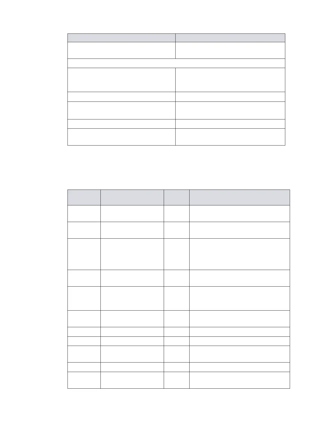
Refer to the following table for Logic Interface connector pins for the electrical
connecons.
Table 11
Logic interface connector pins
Pin Num-
ber
Signal Polarity Use
2 0 V Control reference -
0 V reference for all control and status
signals below
.
3
START/STOP control in-
put
- Connect to Pin 2 to start pump.
4
STANDBY control input/
Serial RX/RS485 A-
-
Connect to Pin 2 to enable standby
speed when serial enable is inacve
and RS485/RS232 switch is in the
RS232 posion.
5 Serial enable -
Connect to Pin 2 to enable the serial
link.
7
FAIL / Serial TX/RS485 B
+
-
Logic high when fail condion exists
and serial enable is inacve and RS485/
RS232 switch is in the RS232 posion.
9 Analogue output Posive
0 ‑ 10 V output proporonal to meas-
ured output
10 Chassis/Screen ‑ Screen
12 Chassis/Screen - -
15 NORMAL status output -
Logic low when pump rotaonal speed
is at normal speed or above
8, 13, 14 Electrical supply: 0 V - -
1, 6, 11 Electrical supply: 24 V -
48 V d.c.
Posive -
08/2021 - ©Edwards Limited
Page 36B8J200880_D
300812671_002_C3
B8J200880_D - Technical data