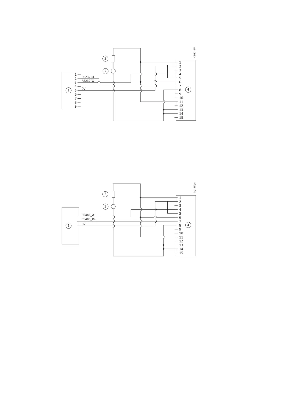
Figure 23 Logic interface connecons - R
S232 serial control
1. RS232 interface on control equipment 2. Oponal 24 V d.c. electrical supply
3. F
use 4. nEXT pump logic interface
1. RS232 interface on control equipment 2. Oponal 24 V d.c. electrical supply
3. Fuse 4. nEXT pump logic interface
Electrical supply connecon to pins 1, 6 and 11 is not required for the nEXT pump as it
has a dedicated pump power supply cable. The fuse is only required if a 48 V d.c.
electrical supply is connected to the logic interface cable.
Figure 24 Logic interface connecons - RS485 serial control
1. RS485 interface on control equipment 2. Oponal 24 V d.c. electrical supply
3. F
use 4. nEXT pump logic interface
1. RS485 interface on control equipment 2. Oponal 24 V d.c. electrical supply
3. Fuse 4. nEXT pump logic interface
5.6.2 Serial enable
To send a serial messag
e over the serial link, serial enable must rst be acvated.
Link the serial enable input signal (pin 5) to pin 2 of the customer logic interface mang
half.
Edwards recommends incorporang this link into the serial communicaons cable so
that the serial enable is only acvated when the serial cable is connected. When the
cable is removed, serial enable will become inacve.
Serial enable acts as an interlock for start commands sent over the serial interface. If the
pump is running in serial control mode (having been sent a serial start command) and
the serial enable subsequently becomes inacve, the pump will trigger a fail condion
and will decelerate to rest. To clear this fail condion, re-acvate the serial enable and
send a serial stop command.
08/2021 - ©Edwards Limited
Page 61B8J200880_D
300812671_002_C3
B8J200880_D - Inst
allaon