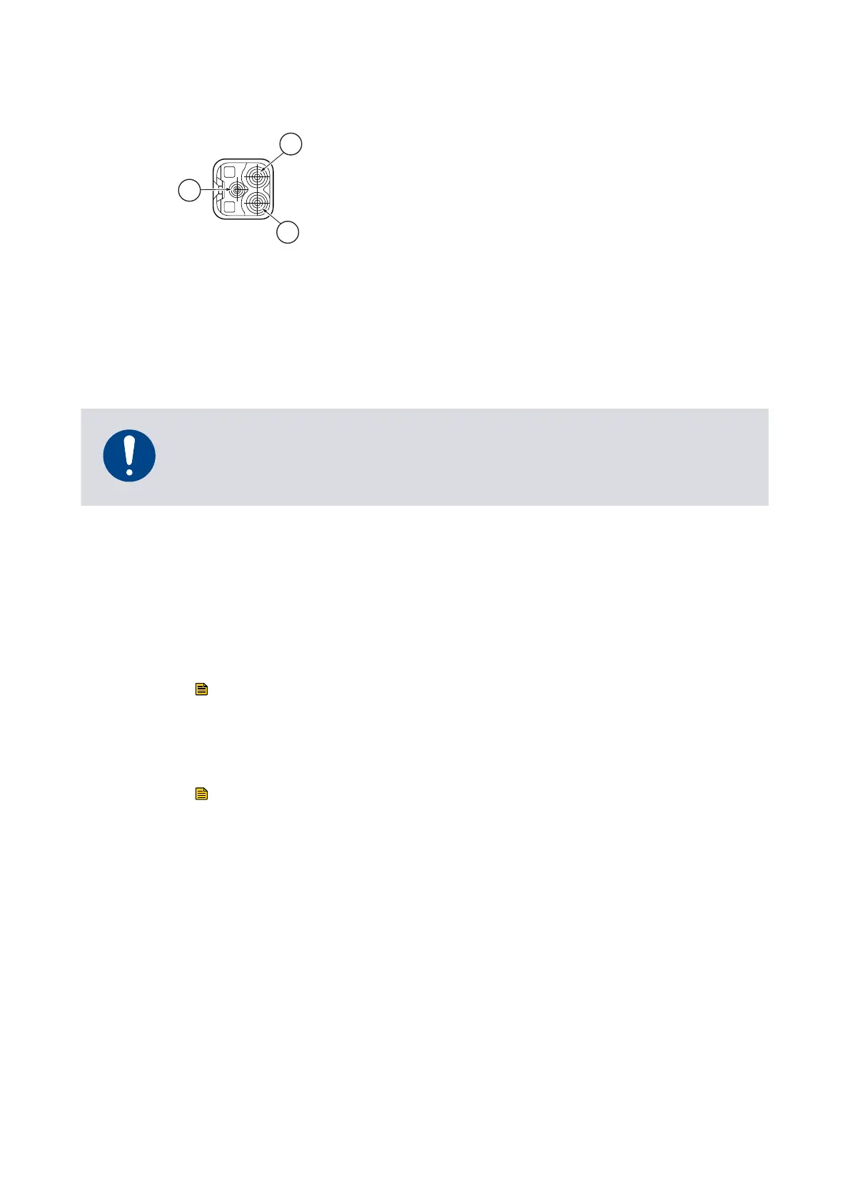
Figure 20 Power supply connector
1. +48V DC Supply 2. 0V Supply
3. Chassis
1. +48V DC Supply 2. 0V Supply
3. Chassis
5.5 Connect the parallel control and monitoring
Connecons for par
allel control and monitoring must be made using a suitable mang
half that is not supplied.
NOTICE:
If using the normal and fail lines t
o drive the coils of d.c. relays, include a back EMF
suppression diode in parallel with each relay coil to protect the pump.
1. Connect the customer control equipment to the control input pins of the customer
logic interface mang half. Refer to Table: Logic interface connector pins, which
idenes the logic interface connector pins.
The control inputs are Start and Standby speed. To acvate either of these control
inputs, connect the control input pin to the 0 V control reference. To start the
pump, connect pin 3 (Start / Stop) to pin 2 (0 V Reference). To stop the pump,
break the connecon between pin 3 and pin 2. To put the pump into standby,
connect both pin 4 (Standby) and pin 3 (Start / Stop) to pin 2 (0 V reference).
Note:
Serial enable is also a con
trol input but is not required in a system operang purely
under parallel control. Make sure that there is no connecon to serial enable (pin
5).
Note:
The RS485/CAN/R
S232 slide switch must be in the (default) RS232 posion to use
the standby or fail parallel interface signals, refer to Connect the serial interface to
the customer control equipment on page 60.
2. To monitor analogue output, connect the customer control equipment to the
pump analogue output (pin 9) and to pin 2 of the cus
tomer logic interface mang
half.
When the pump is shipped, the analogue output is congured to monitor pump
rotaonal speed. To monitor other parameters, re-congure the nEXT pump using
commands over the Serial Interface. Refer to Connecon for serial control and
monitoring on page 59 for further details.
3. To monitor the normal status output, connect the customer control equipment to
the normal st
atus output (pin 15) and to pin 2 of the customer logic interface
mang half.
08/2021 - ©Edwards Limited
Page 58B8J200880_D
300812671_002_C3
B8J200880_D - Inst
allaon